BV512 Vocoder : Tips and tricks

Tips and tricks
Choosing a carrier sound
As always, which carrier sound to choose is a matter of taste and musical context. However, here are a few guidelines to help you get a good result:
Here are some hands-on suggestions for carrier sounds:
*
You could simply start with the initial patch (as set up when you create a new Subtractor device). Open the filter, turn off envelope modulation of the cutoff frequency and raise the Amp Envelope Sustain.
If you want a classic, rich chorus-like sound, use two detuned oscillators - or better still, add a UN-16 Unison device as an insert effect between the Subtractor and the vocoder!
A simple but effective carrier sound setup.
*
With the Malström you can get a stereo carrier signal with no extra devices: simply select the “Sawtooth*16” graintable for both oscillators, detune the oscillators slightly with the Cent controls and raise the Spread parameter to the desired stereo width. No filter routings are necessary.
*
You get this by selecting e.g. a sawtooth wave on the Subtractor, setting the Phase Mode selector to “–” and turning the Phase knob to the left until you get the desired sound. This type of carrier sound lends itself well to monophonic vocoder lines in the lower registers.
*
Try using pure noise (possibly filtered down a bit) for robotic voices, whispering and special effects. It’s also very useful to add a bit of noise to a sawtooth or pulse sound - this makes vocoded speech clearer and more intelligible.
*
A rich drawbar organ sample can also be a cool carrier sound.
*
Try turning up the Attack and Decay controls on the BV512, for smeared, rhythmic or pseudo-random modulation of a pad.
Choosing a modulator sound
The modulator sound should typically have varying level and harmonic content. As we’ve already mentioned, the most typical modulator sounds are vocals or speech and drums or percussion.
*
*
This way you don’t have to program a rhythm pattern. On the other hand, using a Redrum as modulator allows you to create exactly the rhythm you want and fine-tune the sounds and the groove.
Using the modulator as carrier
You can get cool special effects by using the same device both as carrier and as modulator. For example, try processing a Redrum device in the following way:
1.
2.
3.
4.
The output of the Redrum goes into the splitter section of the Spider, and is split into two signals. One signal goes into the carrier input of the vocoder, the other goes into the modulator input.
This is essentially the required connections, but for best results it’s a good idea to add some distortion and/or compression to the carrier signal - this increases the amount of high frequencies in the carrier signal:
5.
6.
Now, the carrier signal will be processed in the distortion device, but not the modulator signal.
7.
*
*
Remember that you can route CV to the Shift parameter on the back of the BV512 - use e.g. a Matrix or an LFO output on a synth device!
Controlling the Hold function
As described in “Hold button”, pressing the Hold button on the front panel “freezes” the current filter spectrum until you deactivate it again. This can be used for creating sample & hold-like effects, stuttering or garbled vocoder sounds:
*
By playing back a gate pattern on the Matrix, the Hold function will repeatedly be turned on and off according to the programmed rhythm in the pattern. Hold will be active for the length of each gate signal.
*
In both cases, the Hold function will be momentary - Hold is on until you release the pedal or key.
Using the individual band level connections
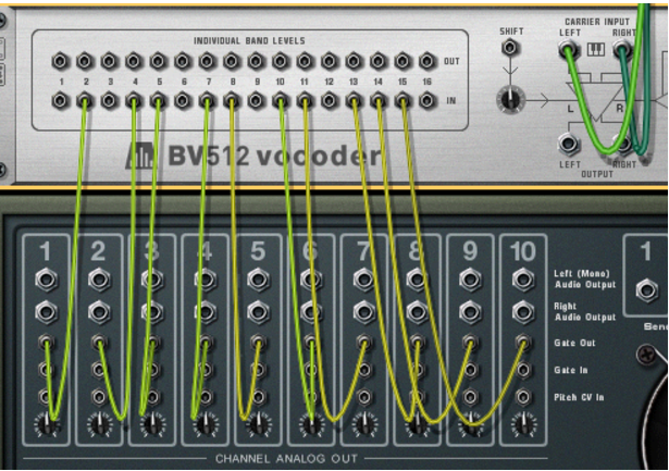
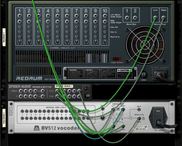
As described in “Individual band levels”, the individual band level connectors on the back are CV output and input jacks. The upper row sends out the CV signals from the envelope followers for the different frequency bands, while the lower jacks are CV inputs for controlling the individual bandpass filters (breaking the internal connection from the envelope followers). There are several interesting things you can do with these connections:
Crosspatching frequency bands
By connecting outputs to inputs in alternative configurations, you can drastically change the result of the vocoding. For example, you could have low frequencies in the modulator signal give high frequencies in the vocoded sound and vice versa. Note:
This means that connecting an output to the input with the same number is not the same as using the internal signal path (no CV cable connected). You can hear this quite clearly in FFT (512) mode: connect all outputs to the corresponding inputs and gradually remove the CV cables while listening to the vocoder sound - the sound will progressively get more detailed.
Extracting CV from the vocoder
You can connect an individual band level output to any CV input on any device. This means you can use the vocoder as an envelope follower, having elements in the modulator sound control a parameter in another device, e.g. an effect. Note:
Controlling vocoder bands from an external source
Connecting a CV source to an individual band input breaks the internal connection from the corresponding envelope follower. This way you can “manually” control the vocoder filters. Some applications:
*
When you play the carrier instrument, one or more of the bandpass filters in the vocoder will automatically open, adding an extra attack to the sound. Useful if you really want to “play” the carrier, rather than just hold a chord.
*
With this connection (and no device connected to the Modulator input), the Redrum will serve as a pattern sequencer, opening and closing different filter bands. To adjust the gate times, set the drum sounds to Gate mode and use the Length parameter. The result is totally different from using the audio signal of the Redrum as modulator.
The vocoder bands are now solely controlled by the gate signals from the drum channels - the modulator input isn’t used.
Note that you can use a Spider CV Merger & Splitter device to split a gate signal, sending it to several bands. Also, note that the velocity of the programmed drum notes govern the level of the corresponding filter bands.
“Playing” the vocoder from a MIDI keyboard
If you have routed MIDI to the BV512, playing notes from C1 and up will control individual filter bands. For example, in 16 band mode, C1 controls band 1, C#1 band 2 and so on up to D#2 (which controls band 16).
Note that with this function, you “play the modulator bands”. However, you still need both a carrier and a modulator signal to get any sound. Typically, you would first record the notes or chords for the carrier device in the sequencer, then create a sequencer track for the vocoder and “play” it from your MIDI keyboard while playing back the recorded carrier notes and at the same time inputting a signal on the Modulator input.
*
Using the BV512 as a reverb
This is a very special trick which can be quite cool. Proceed as follows:
1.
The “vocoder-reverb” is best suited for drums, even though nothing stops you from using it on other sounds.
2.
The Subtractor will automatically be routed to the carrier input. We don’t need a dedicated modulator device in this setup.
3.
4.
This way, our vocoder-reverb will be connected as a regular send effect.
5.
6.
*
*
*
*
*
*
Now we want the Subtractor to play a continuous noise. You could just route MIDI to it, play a note and keep it pressed, but that will probably wear you out in the long run. Better to use a Matrix:
7.
We really only need the Gate connection - the note number isn’t important with the noise patch.
8.
Now the vocoder gets a continuous noise signal as carrier.
9.
10.
This now serves as a balance control between the dry drum sound and the reverb, generated by the voccoded noise! Set it to a suitable reverb level.
11.
12.
You could use the filter cutoff for this as well.
That’s it - a pretty good reverb sound with a lot of control. Although the settings above give the most natural sound, you can vary the sound and create special-FX reverb in the following ways for example:
*
*
*
*
*
Creating a stereo reverb
What you’ve got above is a mono reverb. Here’s how to make it stereo:
1.
2.
3.
The Subtractor output should be routed to a Splitter input on the Spider. One split output should be routed to one of the carrier inputs on the vocoder, the other split output should be routed to the delay. The delay output (mono) should be routed to the other carrier input on the vocoder.
The vocoder will now get a “fake-stereo” noise carrier signal.
4.
5.
When you now start playback on the Redrum, the reverb will be in stereo!

BV512 Vocoder : Tips and tricks