The Combinator : Using the Programmer

Using the Programmer
The Programmer is used for key mapping and setting velocity ranges for instrument devices, and for Modulation Routing; assigning device parameters to the knobs and buttons on the Controller panel.
*
The Programmer appears below the Controller panel.
*
Clicking on a device in the list selects it for editing.
*
*
See “Using Modulation Routing”.
Key Mapping instrument devices
Each instrument device can have its own separate key range, the lowest and the highest key that will trigger the device. This allows you to create splits and layers for instrument devices in a Combi.
1.
2.
The currently selected device key range is highlighted and shown as a horizontal bar under the keyboard display, and as note numbers in the Key Range Hi and Lo fields at the bottom of the Programmer panel. By default, the entire range is selected (C -2 to G 8). Only one device at a time can be selected.
There are several ways you can change the current key range:
*
*
You may have to use the scrollbar at the top to “see” the handles.
*
3.
When done, the device will only play back notes in the set key range.
*
For example playing notes below C 2 could trigger a device playing a bass sound, whereas playing notes above C 2 could trigger a device playing a pad sound.
*
This given that no velocity ranges have been set up - see below.
*
About the Transpose function
The Transpose field in the right bottom corner allows you to transpose the currently selected instrument device. It will not shift the key mapping, just the pitch of the selected device. Range is +/- 3 octaves, in semitone steps.
About the keyboard
You can use the keyboard to audition selected instrument devices by pressing [Option] (Mac) or [Alt] (Windows) and clicking on the keys.
About the Receive Notes/MIDI Performance Controller checkboxes
In the lower left corner of the Programmer there is a Receive Notes field with a corresponding checkbox, and below there are checkboxes for all standard MIDI Performance controllers (Pitch Bend/Mod Wheel/Breath/Expression/Sustain Pedal/Aftertouch).
*
*
If a non-instrument device is selected this checkbox is always deactivated.
*
All are on by default.
Setting Velocity Ranges for instrument devices
When instrument devices are set up so that their key ranges overlap – completely or partially – you can use velocity switching to determine which devices should be played back depending on how hard or soft you play on your MIDI keyboard.
This is done by setting up velocity ranges.
Each time you press a key on your MIDI keyboard, a velocity value between 1-127 is sent to Reason. If you press the key softly, a low velocity value is sent and if you press it hard, a high velocity value is sent.
This velocity value determines which devices will be played and which will not.
1.
By default, the entire range is selected (0 - 127).
2.
3.
About overlapping Velocity Ranges
You can set overlapping velocity ranges. Here’s an example of how this can work:
*
*
*
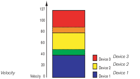
Now, velocity values between 41 and 60 will trigger notes from both Device 1 and Device 2. Likewise, velocity values between 81 and 100 will trigger sounds from Device 2 and Device 3.
About full and partial velocity ranges
You can see which devices have modified velocity ranges in the key map display:
The device has a partial velocity range, which is indicated by stripes.
Using Modulation Routing
The Modulation Routing section allows you to assign any parameter or function in devices included in a Combi to any of the virtual Rotary and Button controls on the Controller panel. You can also control Combi Programmer parameters by connecting external CV modulation sources to any of the four Programmer CV Inputs on the back of the unfolded Programmer panel.
About Rotary and Button controls
The virtual Rotary and controls operate much like the equivalent controls on the real devices:
*
*
Worth noting is that there are buttons on several Reason devices that will step through a series of values, for example LFO Waveform buttons. If LFO Waveform is assigned to one of the virtual Buttons you will only be able to switch between two of the six LFO waveforms (which waveforms is determined by the Min/Max range).
*
Most sliders and rotary knobs on the actual devices have the standard 0-127 or
-64 to 63 range. Selectors and spin controls can have any value range.
About the Programmer CV Inputs
On the back of the Programmer panel are four CV Modulation Inputs for connecting external sources to modulate any of the parameters that are accessible in the Target section in the Programmer, see “Programmer CV Inputs”.
Assigning parameters to a control
This is done as follows:
1.
The name of the selected device is now shown in the Modulation Routing Device field. The Modulation Routing section contains four columns:
*
The last two fields are unassigned by default.
*
*
*
2.
On the pop-up that appears, all the available parameters for the device are listed.
3.
The parameter is now assigned, and the name of the parameter is shown in the Target column for the corresponding control.
4.
5.
6.
By default the maximum available range is set.
7.
This means that you can create multi-function controls that operate simultaneously on several parameters. E.g. if you have two Subtractors and a Malström in a Combi you could create a “master” filter cutoff knob, that controls this parameter for all three devices.
Naming a control
When you make modulation routing assignments, you should give the associated control a descriptive name that reflects what it does, for example Vibrato On/Off or the name of the parameter that it controls.
This is done by clicking the label on the Controller panel and typing in new name.
CV Connections
CV connections between devices in the Combi are saved with the Combi patches. This is also true for CV connections between devices in Combi and the Combi itself - e.g. if you have connected a Matrix in the Combi to one of the CV inputs on the back of the Combi panel.
The following CV connectors can be found at the back of the Combinator:
Sequencer Control Inputs
The Sequencer Control CV and Gate inputs allow you to play the Combinator from another CV/Gate device (typically a Matrix or a RPG-8). The signal to the CV input controls the note pitch, while the signal to the Gate input delivers note on/off along with velocity.
Modulation Inputs
In this section you will find standard CV Mod Wheel and Pitch Bend modulation inputs, as well as modulation inputs for the four Rotary controls.
*
Programmer CV Inputs
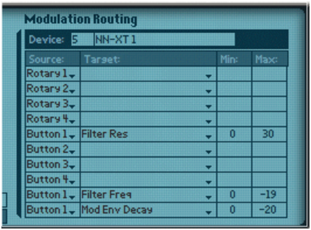
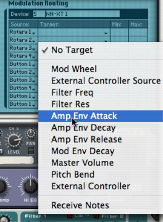
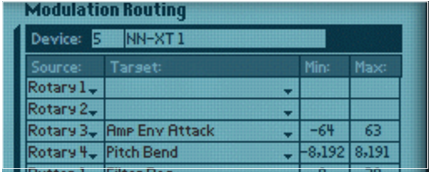
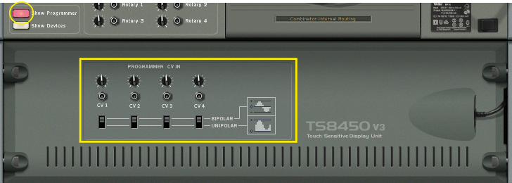
Here you can connect external CV modulation sources for modulating any of the Target parameters in the Programmer (see “Using Modulation Routing”). Next to each CV Input are one sensitivity knob and one polarity switch that work as follows:
For example, if you have connected a CV signal from an envelope generator, the switch should be set to Unipolar. If you are modulating from a standard LFO, the polarity switch should be set to Bipolar.

The Combinator : Using the Programmer