|
•
|
|
|
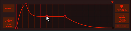
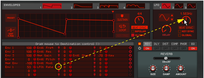
See “Recording display movements in the sequencer” for tips about automating display movements.
|
|
•
|
|
|
|
|
Try this together with the “Stretch” algorithm in the Harmonics section to create realistic metallic sounds.
|
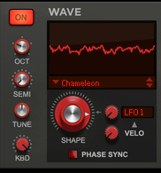
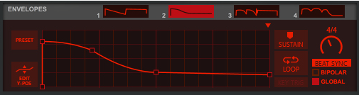
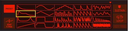
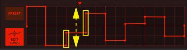
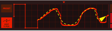
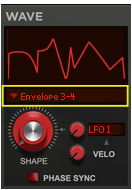
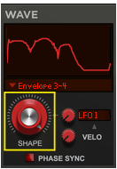
This is a special mode where you can manually draw your waveforms in the Envelope 3 and Envelope 4 windows and then gradually crossfade between the drawn waveforms using the Shape knob. See “Using the Envelope 3 and Envelope 4 curves as Sound Engine waveforms” for information on how to draw your own waveforms.
A pure sinewave signal at Shape=0% gradually fed back internally at an 1:1 ratio. The feedback signal is filtered before fed back to the carrier signal. If you modulate the Shape parameter from e.g. an LFO you will get a similar result as when using the FM FB Noise waveform without Shape modulation, see “Noise > FM FB Noise” below.
The User Wave options let you use the external sample you have loaded in the User Wave section (see “The User Wave and Mixer section”). The oscillator then generates and plays back wavetables (grains) of that sample. The “User Wave Smooth” algorithm uses a crossfaded loop within each grain, which produces a smoother character to the sound. Set the playback position in the sample with the Shape knob. Modulate the Shape parameter, for example from a negative Envelope ramp, for continuous movement in the sample.
|
|
|
•
|
|
•
|
|
•
|
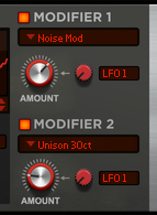
Here, an internally fed back sinewave signal at an 1:1 ratio modulates the waveform (same signal type as in the “FM > FM Feedback” Waveform).
|
•
|
To make the formant static in the frequency spectrum, regardless of which note you play, modulate the Amount parameter using the “-KEY” (inverted) modulation source with a fairly high value (see “Amount Modulation” below). This is especially useful if you are using an acoustic instrument sample as User Wave in the Oscillator section.
|
|
|
|
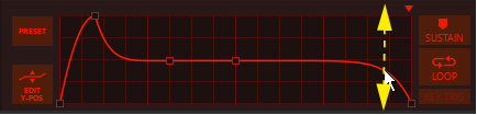
See “Recording display movements in the sequencer” for tips about automating display movements.
|
|
•
|
|
•
|
|
•
|
|
•
|
|
•
|
|
•
|
|
•
|
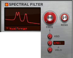
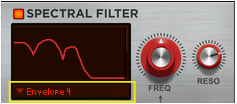
This is a special mode where you can manually draw your own filter curve in the Envelope 4 window. You then control the cutoff/center frequency with the Freq knob and the resonance with the Reso knob. See “Using the Envelope 4 curve as a Spectral Filter curve” for information on how to draw your own filter curves.
This utilizes a filter generated from FFT analyses of the external sample you have loaded in the User Wave section (see “The User Wave and Mixer section”). Transpose the formant up/down in the frequency spectrum with the Freq knob and change the filter’s position in the sample with the Reso knob.
|
|
To create a classic “vocoder” effect, load a vocal/speech sample in the User Wave section. Then, set the Freq knob to 50%, the Reso knob to 0% and the KBD knob to 0%. Then, have one of the Envelopes modulate the Reso parameter using the Modulation Bus (see “The Modulation Bus section”). Create a positive ramp (inverted sawtooth) envelope and set the Reso modulation amount to 100%.
|
|
|
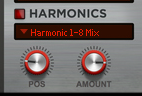
The Harmonics section offers extensive modulation possibilities of the partials of the signal. For most algorithms the partials’ characteristics is displayed in the Spectral Filter display, see “Spectral Filter display”.
|
•
|
|
•
|
|
|
|
•
|
|
•
|
The Harmonic Lag A-R algorithm is designed especially for use with the User Wave algorithm in the Spectral Filter (see “User Wave”) to create vocoder effects. The Harmonic Lag A-R algorithm controls the Spectral Filter - so the Spectral Filter has to be on for this to work!
|
•
|
|
•
|
|
•
|
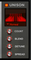
If Phase Sync is active in the Oscillator (see “Phase Sync”), all signals in the Unison function get the same relative start phases each time you play the same note. The original signal always has the phase 0 degrees.
|
|
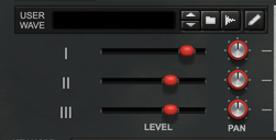
The User Wave and Mixer section is where you can sample (or load an external sample) to use in the Oscillators (see “User Wave/User Wave Smooth”) and/or in the Spectral Filter (see “User Wave”). In the Mixer you can mix and pan the signals from the three Sound Engines before sending them to the Filter, Amp and Multi FX sections.
See the “Sampling” chapter for more information about setting up and using Reason for sampling.
See “Editing samples” for more information about editing samples in Reason.
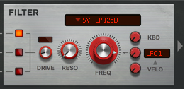
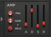
If deactivated, the signal bypasses the Filter and goes straight to the Amp section, see “The Amplifier section”.
|
|
Use one of the Envelopes (see “The Envelopes section”) as modulation source to create a Filter envelope.
|
|
|
|
|
|
|
|
|
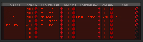
See “The Modulation Bus section” for details on how to assign the Envelopes to the desired destination(s).
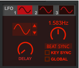
The LFO section features three separate general purpose LFOs, that can be assigned to control selectable parameter(s) in the Modulation Bus section, see “The Modulation Bus section”.
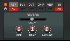
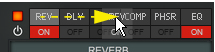
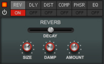
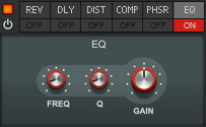
The Effects section features six different effect modules that can be freely reordered by dragging & dropping. Most of the effect parameters are also available as destinations in the Modulation Bus, see “The Modulation Bus section”.
|
•
|
|
•
|
|
•
|
|
•
|
|
•
|
|
•
|
|
•
|
|
•
|
|
•
|
|
•
|
|
•
|
|
•
|
|
•
|
|
•
|
|
•
|
|
•
|
|
•
|
|
•
|
|
•
|
|
•
|
|
|
|
•
|
|
•
|
|
•
|
|
|