Grain Sample Manipulator : Panel reference

Panel reference
The Sample section
Here is where you load/sample and configure the audio that should serve as the base for the granular synthesis.
Loading/sampling
*
*
See the “Sampling” chapter for more information about setting up and using Reason for sampling.
*
See “Editing samples” for more information about editing samples in Reason.
*
Setting the sample range
First you could decide how much of the original sample you want to use - and where in the sample you want to work:
*
To scroll, click and drag between the orange sample range markers. To zoom, click and drag any of the sample range markers sideways. The set Sample range is automatically updated and displayed in the waveform display.
*
*
Setting the sample start and end
*
*
The green triangular “flag” on the Sample Start marker shows the current playback direction. If the Sample Start marker should be to the right of the Sample End marker, the sample will play back in the opposite direction.
*
*
Motion
Motion controls the way the Position marker (“playhead”) is played back in the original sample. The Motion modes work in conjunction with the Sample Start/End markers in the waveform.
*
In Freeze mode, the sample is played back at (and around) the Sample Start marker position. There is no Sample End marker in this mode. Note that if you have selected the Tape algorithm (see “Tape”), there will be no sound.
In One Shot mode, the sample is played back (from the Sample Start marker to the Sample End marker) in its entirety each time you press a key.
In FW Loop mode, the sample is looped forward (from the Sample End marker to the Sample Start marker) for as long as you hold down a key.
In FW-BW Loop mode, the sample is looped back and forth between the Sample End marker and the Sample Start marker for as long as you hold down a key.
In End Freeze mode, the sample is played back once from the Sample Start marker to the Sample End marker and then played back at (and around) the Sample End marker position. Note that if you have selected the Tape algorithm (see “Tape”), there will be no sound after you reached the Sample End marker.
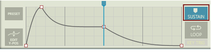
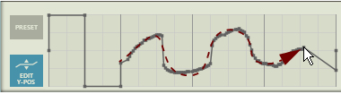
In Envelope 1 mode, the sample is played back between the Sample Start marker and the Sample End marker according to the Envelope 1 curve (see “The Envelopes section”). The Sample Start position is represented by the minimum Y value and the Sample End position is represented by the maximum Y value in the Envelope display.
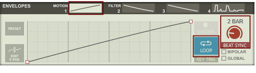
The Envelope 1 mode is also the mode to use if you want to play back and loop the sample in sync with the Reason sequencer. Use a straight ramp (up) in Envelope 1, activate Beat Sync and set the sync to a suitable bar length, see “Looping the envelope”.
Speed
The Speed control determines how fast the play position moves in the waveform.
*
Depending on which Motion mode and Playback Algorithm is currently selected, the sonic result may vary heavily.
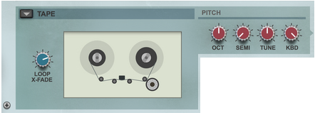
If you have selected the Tape algorithm (see
“Tape”), the Speed knob also affects the pitch. Note that the Speed can be set all the way down to 0%, i.e. “stop”. Great for Tape Stop effects, for example.
*
Jitter
The Jitter function modulates the sample playback position minutely and randomly. The Jitter function can be great for generating “chorus”-like effects and to make a sound more “alive”, depending on the other settings in the sound.
*
At 0%, the timing and playback position is completely accurate and at 100% it is completely random.
Global Position
*
This function is great for rhythmic and vocoder-like sounds etc.
If not active, new voices will always start playing back from the Sample Start marker.
Root Key
A sample is automatically analyzed for its original pitch at the Sample Start position. The analyzed pitch is displayed in the Analyzed display in the Root Key section. If you move the Sample Start marker, the sample is automatically re-analyzed.
*
This will automatically place the analyzed Root Key on the correct note in the keyboard range.
*
The Playback Algorithms section
Here is where you select which Playback Algorithm to use for manipulating the sample. Each of the Playback Algorithms produce very different sonic results and have different unique parameters.
*
*
Spectral Grains
The Spectral Grains playback algorithm uses FFT analysis to analyze the frequency content (partials) of the original sample. You can then stretch the generated signal by pitch-shifting the partials, and also filter out inharmonic partials. This way you could continuously transform inharmonic signals into harmonic signals, for example. You can also draw your own formant curves in the spectrum display to give the sounds different pitches/characters.
This pitch-shifts inharmonic partials towards the closest harmonic partials. At 0% the sound is almost unaffected and at 100% the sound contains only harmonic partials.
Instead of pitch-shifting inharmonic partials towards harmonic ones, as the Snap control above does, the Filter control filters out the inharmonic partials and keeps the harmonic ones. Since the filter slopes are not brickwall shaped some of the inharmonic partials (if any) will remain audible even at 100%.
This sets the accuracy (and speed) of the frequency analysis. “0” is the fastest detection, but this also leaves out detection of low frequencies. “4” is the most accurate detection. However, it’s also slower since it also detects low-frequency material (which takes longer to detect).
With the Curve tool you can draw your own formant curves in the frequency spectrum. Drawing above the pink area means the partials are amplified, and drawing below the pink area means the partials are attenuated.
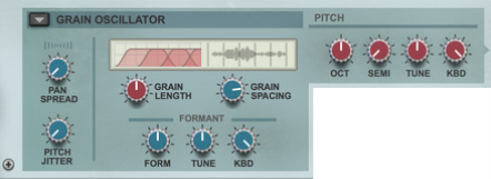
Set the gain/attenuation amount of the drawn formant curve (see “Curve” above). At 0% the curve is completely flat.
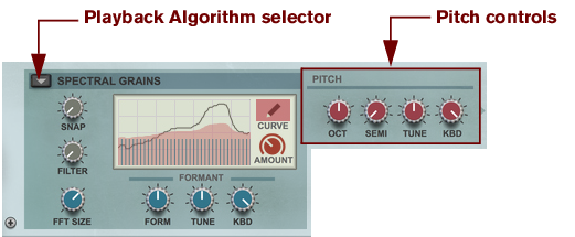
Sets the initial pitch of the sample, together with the Root Key setting (see “Root Key”). If Snap and Filter are both set to 0%, the Root Key and Formant controls the pitch of the signal. This also means that the Pitch parameters (see “Pitch controls”) and Pitch wheel (see “Pitch”) have no effect. To have the Formant track the keyboard in a musical way, make sure the Formant Kbd parameter (see below) is set to 100%.
When you raise the Snap or Filter parameters towards 100% the sound gradually adapts to the Pitch settings instead, and the Root Key and Formant parameters now affect the tone color instead.
Here you can fine-tune the formant curve to adjust the pitch to the Oscillator pitch (see “The Oscillator section”).
Here you set how much you want the formant to track the keyboard. 0% means no keyboard tracking and 100% means full 1:1 keyboard tracking. If the Snap and Filter parameters (see above) are both set to 0%, make sure the Formant Kbd is set to 100% to make the audible pitch track the keyboard one semitone per note.
Grain Oscillator
The Grain Oscillator plays back a mix of two very short grains of the original sample. The grain playback rate corresponds to the oscillator pitch. This means the original pitch (Root Key/Formant) of the sample doesn’t affect the pitch of the sound, but the timbre.
Here you set how much you want the grains to be panned in the stereo panorama. 0% means the signal will be unaffected and 100% means every other grain will be panned hard left and hard right. Great for nice stereo effects and for the impression of an added stereo sub-oscillator, depending on the settings. Note that the pitch of the panned signal becomes 1 octave lower than the original signal due to the fact that every other grain is panned.
Changes the pitch of every grain. The pitch modulation character is “smooth random”.
Sets the lengths of the grains and also the crossfade amount. At 0% you get the shortest grains and almost no crossfade at all. This means the sound could be a little gritty at this setting. At 100% you get longer grains, that also overlaps each other with a smooth crossfade.
Sets the spacing in the original sample between the two played back grains. High Spacing values render more even sound character throughout the played notes - almost like a wavetable synth - since a lot of audio data in the original sample is skipped. Less spacing normally creates more varying sound character between each played note.
Sets the formant’s initial frequency. Turn this knob to change the tone color of the sound. At high Grain Spacing values (see above) the effect of changing the Formant could be similar to the classic “oscillator sync” sound. To have the Formant fully track the keyboard, make sure the Formant KBD parameter (see below) is set to 100%.
Here you can fine-tune the formant curve.
Here you set how much you want the formant to track the keyboard. 0% means no keyboard tracking and 100% means full 1:1 keyboard tracking.
Long Grains
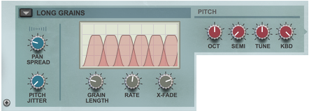
The Long Grains playback algorithm plays back fairly long grains of the original sample. This means that it’s the original pitch of the sound (Root Key) that affects the pitch, along with the Pitch settings (see “Pitch controls”).
The display shows the effects of the Grain Length, Rate and X-Fade settings.
Here you set how much you want every other grain to be panned in the stereo panorama. 0% means the signal will be unaffected and 100% means every other grain will be panned hard left and hard right. Great for nice stereo effects!
Changes the pitch of every grain. The pitch modulation character is “smooth random”.
Sets the lengths of the grains. At 0% you get the shortest grains and towards 100% you get longer grains.
This controls the playback rate of the grains.
Here you set the crossfade between the grains. At 0% there is minimal crossfade, which will give the signal a gritty or “popping” character at the playback start and end of each grain.
Tape
The Tape playback algorithm plays back the sample the old-fashioned “tape-style” way, where playback speed and pitch are linked. If playback speed is zero (in Freeze and End Freeze Motion modes for example), no sound will be heard - but you can drag, modulate or automate the playback position for scrubbing and tape stop effects.
Sets the crossfade amount if you have selected FW Loop or FW-BW Loop as Motion type (see “Motion”)
*
*
If you have selected “Envelope 1” as Motion type (see “Envelope 1”), the Speed (see “Speed”) and Pitch settings (see “Pitch controls”) have no effect. The sample will play back at the same pitch regardless of which note you play.
Pitch controls
Sets the pitch in octave steps.
Range: 5 octaves.
Sets the pitch in semitone steps.
Range: 12 semitones (one octave).
Changes the pitch in steps of 1 cent.
Range: +/- 50 cents (down or up half a semitone).
Sets how much the pitch should track incoming MIDI Notes.
Range: 0% (no tracking (constant pitch)) to 100% (1 semitone per key).
*
In the Spectral Grains playback algorithm (see “Spectral Grains”), the Pitch controls have no effect if Snap and Filter are set to 0%. To get full effect of the Pitch controls, set Snap or Filter to 100%.
The Oscillator section
The Oscillator can be used in addition to the sample playback. The oscillator features a number of selectable waveforms and a modulation control, which affect the signals differently depending on selected waveform. The oscillator pitch always tracks the keyboard to 100%. This makes it perfect as a pitch reference for the sample signal.
On/Off
*
Oct
*
Range: 5 octaves.
Waveform and Mod
*
The waveforms are:
A pure sinewave at Mod=0%, gradually transformed towards a sawtooth type signal at Mod=100%.
A triangle wave at Mod=0%, gradually transformed towards a sawtooth type signal at Mod=100%.
A lowpass-filtered sawtooth wave at Mod=0%, gradually transformed to a pure sawtooth signal at Mod=100%.
A 50% duty cycle square wave at Mod=0%, gradually pulsewidth-modulated to a 0% duty cycle pulse wave
(silence) at Mod=100%.
*
A level-compensated lowpass-filtered noise at Mod=0%, gradually transformed to white noise at Mod=100%.
A noise-modulated sinewave. The Mod knob controls noise bandwidth. At Mod=100%, the oscillator produces pure noise. Turning the knob counter-clockwise towards 0% gradually narrows the noise bandwidth until a slightly modulated sinewave is produced.
The Filter section
The signals from the Playback Algorithms section and the Oscillator section can be individually mixed and routed through the Filter section. The Filter section features four different filter types.
Routing buttons
*
To bypass the signals from the Filter section, click the buttons with the triangle pointing upwards or downwards.
Filter type
*
A highpass filter with a 12dB/octave slope.
A bandpass filter with 12dB/octave slopes.
A lowpass filter with a 12dB/octave slope.
A ladder-type lowpass filter with a 24dB/octave slope.
Freq
*
Reso
*
Env 2
*
Since this is a “hardwired” connection from Envelope 2 you don’t need to use the Modulation Bus for envelope modulating the cutoff/center frequency.
Vel
*
Kbd
*
At 0%, the filter frequency is static regardless where on the keyboard you play. At 100% the filter tracks the keyboard 1:1, i.e. one semitone per note.
The Amplifier section
The Amplifier section contains a standard ADSR envelope which controls the amplitude of the signals from the Playback Algorithms and Oscillator sections equally. The picture below shows the various stages of the ADSR envelope:
The ADSR envelope stages.
A(ttack)
When you play a note on your keyboard, the envelope is triggered. This means it starts rising from zero to the value set with the Gain knob (see below). How long this should take, depends on the Attack setting. If the Attack is set to “0”, the Gain level is reached instantly. If the Attack value is raised, it will take longer time before the Gain level is reached.
D(ecay)
After the Gain level has been reached, the level starts to drop. How long this should take is governed by the Decay parameter.
If you want to emulate the volume envelope of a note played on a piano for example, the Attack should be set to “0”, the Decay parameter should be set to a medium value and the Sustain level should be set to “0”, so that the volume gradually decreases down to silence, even if you keep holding the key down. Should you want the decay to drop to some other value than zero, you raise the Sustain parameter.
S(ustain)
The Sustain parameter determines the level the envelope should rest at, after the Decay stage. If you set Sustain to full level, the Decay setting is of no importance since the volume of the sound is never lowered.
If you want to emulate the volume envelope of an organ, you theoretically only really need to use the Sustain parameter set to full level, as a basic organ volume envelope instantly goes to the maximum level (Attack “0”) and stays there (Decay “0”), until the key is released and the sound instantly stops (Release “0”).
But often a combination of Decay and Sustain is used to generate envelopes that rise up to the Gain level, then gradually decreases to finally land to rest on a level somewhere in-between zero and the Gain level. Note that Sustain represents a level, whereas the other envelope parameters represent times.
R(elease)
The Release parameter works just like the Decay parameter, except it determines the time it takes for the volume to drop back to zero after you release the key.
Gain
*
This is the maximum level the envelope will reach after the Attack stage is completed (see above).
*
Vel
*
Pan
*
*
The Envelopes section
The Envelopes section features four separate polyphonic (one per voice) general purpose envelope generators, that can be assigned to control selectable parameter(s) in the Modulation Bus section. The first two envelopes (Envelope 1 and Envelope 2) are also hardwired to the Motion and Filter Frequency destinations respectively.
The Envelopes are extremely flexible, and you can draw your own custom modulation shapes by clicking and drawing in the display area. There are also a number of preset shapes that you can use as starting points (or use as is). If you use Loop mode, you could turn the envelope into a kind of LFO.
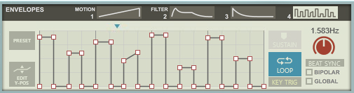
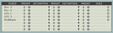
See “The Modulation Bus section” for details on how to assign the Envelopes to the desired destination(s).
Envelope 1, 2, 3 and 4
*
 
Envelope 1 and Envelope 2 are also hardwired to the Motion and Filter Frequency destinations respectively.
Preset
1.
2.
Let’s select a standard ADSR style of envelope curve:
 
Adding a Sustain stage
*
The vertical blue marker that appears indicates where the envelope will stay sustained until you release the key.
*
*
Adding and removing envelope points
*
*
Changing the envelope curve shape
*
Looping the envelope
*
If there was previously a sustain stage in the envelope, this will automatically be disabled when you click the Loop button.
Here we have edited a stepped curve from the Presets. We have also enabled Beat Sync and set the length/rate to 4/4. This means that each step in the curve now represents an 1/8th note.
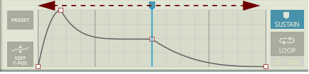
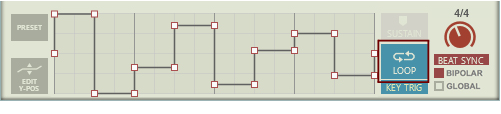
Another useful application for looped envelopes is to sync the sample playback to the Reason sequencer when using the Envelope 1 Motion mode (see “Envelope 1”):
1.
2.
Playing back Reason’s sequencer now plays back the sample synced to the sequencer Tempo.
Editing levels only
*
In this mode you cannot change the time positions of the envelope points, only their levels (height). This is extra useful with a stepped Preset curve, because dragging up or down will change the value of an entire segment, turning the Envelope into a pseudo-sequencer.
*
Adjusting the level of a segment.
Creating “free form” envelope curves
As a special feature in the Edit Y-Pos mode, you can also draw “free form” curves:
*
*
The LFO section
An LFO (Low Frequency Oscillator) is used for generating cyclic modulation. A typical example is to have an LFO modulate the pitch of a signal to produce vibrato, but there are countless other applications for LFOs.
The LFO section features three separate general purpose LFOs, that can be assigned to control selectable parameter(s) in the Modulation Bus section.
*
*
Besides the standard waveforms (sine, triangle, pulse, etc.) there are random, slope and stepped waveforms. The shape of the waveforms are shown in the display.
*
*
The Rate parameter now controls the time divisions.
*
*
*
Turn clockwise for longer delay times.
The Effects section
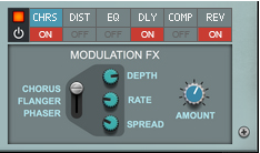
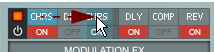
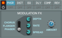
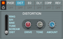
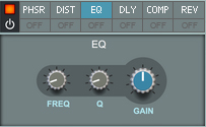
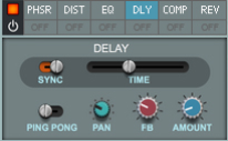
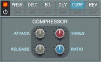
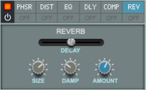
The Effects section features six different effect modules that can be freely reordered by dragging & dropping. Most of the effect parameters are also available as destinations in the Modulation Bus, see “The Modulation Bus section”.
At the top of the Effects section are six Effect buttons. Click any of these to bring up the control panel for the corresponding effect. Below the Effect buttons are the On/Off buttons for the individual effects. Click these to activate the effects.
Reordering the effects
*
Moving the Chorus effect to another position in the effects chain.
You can reorder the effects at any time.
Phaser/Flanger/Chorus
This is a stereo Phaser/Flanger/Chorus.
*
The selected effect type is displayed on the Effect button.
Sets the depth of the selected effect. To get a static sound, set Depth to zero.
Sets the rate/speed of the modulation.
Sets the stereo width of the effect.
Sets the Dry/Wet amount of the effect.
*
Distortion
The Distortion effect features six different types of distortion.
*
“Dist” produces a dense, rich analog type of distortion.
“Scream” produces a less bright type of distortion.
“Tube” emulates a tube type of distortion.
“Sine” is a sine shaping distortion.
“S/H” gives the effect of sample rate reduction.
“Ring” is a ring modulator effect.
Sets the overdrive/feedback level of the selected distortion.
This is a lowpass filter and sets the tone of the selected distortion.
Sets the Dry/Wet amount of the distortion.
EQ
The EQ effect is a single band parametric equalizer with adjustable Q-value and Gain.
Sets the center frequency of the EQ band.
Sets the bandwidth of the EQ band, from wide to narrow.
Sets the gain/attenuation of the EQ band, from -18dB to +18dB.
Delay
This is a stereo delay, routed as a send effect.
Activate Sync to sync the delay time to the main sequencer Tempo.
This sets the time between the delay repeats. If Sync is active (see above), the Time parameter now controls the time divisions.
Activate Ping Pong to have the delay repeats alternating between left and right in the stereo panorama. The effect is also dependent on the Pan parameter (see below).
Sets the panning of the delay repeats in the stereo panorama. If Ping Pong is active (see above) the Pan knob controls the panning of the initial delay repeat as well as the total stereo spread of the remaining repeats.
The FB (feedback) parameter determines the number of delay repeats.
Use this parameter to adjust the send level to the Delay effect.
*
Compressor
This is a stereo compressor.
This governs how quickly the compressor will apply its effect when signals rise above the set threshold. If you raise this value, the response will be slower, allowing more of the signal to pass through the compressor unaffected. Typically, this is used for preserving the attacks of the sounds.
When the signal level drops below the set threshold, this determines how long it takes before the compressor lets the sound through unaffected. Set this to short values for intense, “pumping” compressor effects, or to longer values for a smoother change of the dynamics.
This is the threshold level above which the compression sets in. Signals with levels above the threshold will be affected, signals below it will not. In practice, this means that the lower the Threshold setting, the more the compression effect.
This specifies the amount of gain reduction applied to the signals above the set threshold.
Reverb
This is a stereo reverb, routed as a send effect.
This governs the length of the reverb effect.
Sets the emulated room size, from small room to large hall. Middle position is the default room size.
Lowering this parameter results in a closer and gradually more “canned” sound. Raising the parameter results in a more spacey sound, with longer pre-delay.
Raising the Damp value cuts off the high frequencies of the reverb, thereby creating a smoother, warmer effect.
Use this parameter to adjust the send level to the Reverb effect.
If you play a note, have a long delay Decay time and turn down Amount, the reverberation will continue.
The Modulation Bus section
The Modulation Bus section is used for routing a modulation Source to one or two modulation Destinations each. This creates a very flexible routing system that complements the pre-wired routing in Grain.
The Modulation Bus section in Grain is derived from the one in the Reason Thor Polysonic Synthesizer device, so if you are familiar with Thor, you will quickly find your way around in Grain’s modulation bus.
There are eight “Source –> Destination 1 –> Destination 2 –> Scale” busses, of which the first four have pre-assigned sources. However, these four pre-assigned sources can be easily changed if you like.
A Source parameter can modulate two different Destination parameters per bus (with variable Amount settings). Each bus also has a Scale parameter that affects the relative modulation Amount for both Destinations.
*
 
1.
The following parameters can be used as modulation Sources:
Modulation Bus Source parameters.
2.
*
3.
The arrow symbol turns blue.
4.
Assigning LFO 1 Rate as a Destination for Envelope 1.
As you hover over a valid destination control on the panel, the parameter name is automatically displayed in the Destination box in the Modulation Bus.
5.
*
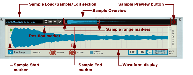
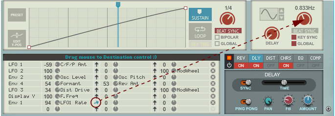
Dragging to the Waveform Display (see “The Sample section”) will always assign the playback Position
parameter. To assign the sample Start Position or End Position, select the parameter from the list (see below).
*
The following parameters can be used as modulation Destinations:
Modulation Bus Destination parameters.
6.
7.
8.
The available Scale parameters are the same as the Source parameters, see “Modulation Bus Source parameters.”.
9.
Both positive and negative Scale Amount values can be set (+/- 100%). If you, for example, are using the Mod Wheel as Scale parameter and don’t want any modulation when the Mod Wheel is set to zero, set the Scale Amount parameter to 100%. Then, there will be no effect when the Mod wheel is set to zero, and full modulation when the Mod Wheel is all the way up.
*
*
*
Modulation example patches
The factory patches for Grain features a folder named “Templates”. In this folder you will find a number of patches that show typical modulation examples, to make it easier to get the hang of how to create your own patches.

Grain Sample Manipulator : Panel reference