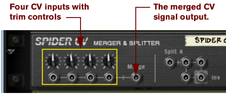
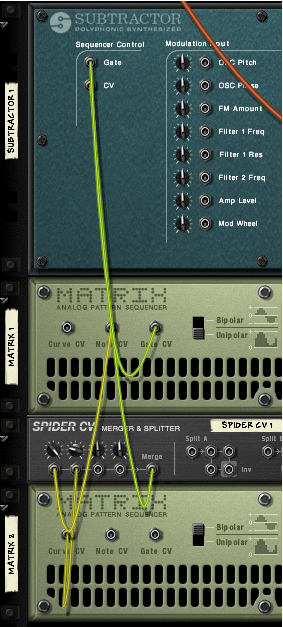
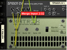
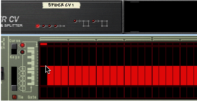
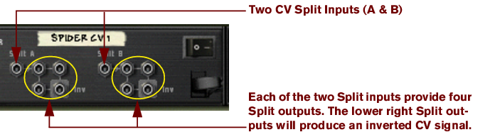
Spider CV Merger & Splitter The Spider CV Merger & Splitter is not an effect device, but a utility. It has two basic functions: To provide one merged CV output from up to four CV input sources. To split CV or Gate inputs into several outputs. Two inputs, A and B, are provided, each with four outputs, where one of the outputs will invert the polarity of the control signal. One reason for having two splitable inputs is to make it possible to split Gate and Note CV, to control several instrument devices with one Matrix for example. There are no controls on the front panel of this device, only CV signal indicators. The four horizontal indicators light up to indicate signals connected to the corresponding merge input. The two indicators to the right indicate signals connected to the corresponding split inputs. Merging CV On the back panel of the Spider there are several CV connectors. The left half of the panel contains four CV/Gate input connectors with associated trimpots, and to the right of these, one merged CV output. The merged CV output will produce a CV signal that represents the “sum” of all connected CV inputs. A few things to note: • Gate CV signals typically trigger notes or envelope cycles and are normally routed to a Gate input. • CV signals typically control note pitch or for modulating parameters and are typically routed to CV Note or Modulation inputs. There are no strict rules involved, but the facts mentioned above means that it is generally better to stick to using either Gate CV signals or CV signals but not a mixture when merging. simply because the CV/Gate signals usually go to different input destinations. For instance, merging Note CV and Gate CV from a Matrix does not make much sense if you want to use Matrix to play melodic patterns via the Sequencer Control inputs of an instrument device. There would only be one merged output whereas the instrument device would need a separate Gate and Note CV signal to work properly. Practical uses of merging CV The practical applications of merging CV are perhaps less obvious compared to splitting CV. But there are numerous applications for a merged CV control output, a few of which are listed below: You can create interesting modulation effects by merging several Modulation outputs from LFO’s and other CV modulation sources. For example, merging the Modulation outputs from several LFO’s would produce a “mixed modulation” output. This merged output signal could be likened to a “super LFO” capable of generating several modulation cycles simultaneously, each with a different waveform and modulation rate! In addition to this, by using the trim control for each CV input, you have full control over the amount of modulation applied by each LFO. The above example could of course also include Curve CV outputs from a Matrix or Mod Outs from Malström etc., in short any CV Modulation output. Use the ECF-42 Filter to apply envelope controlled filter effects. This can create the sound of “synthesized” percussion, and other interesting effects. This is done using the following method: 1. Connect the audio outputs of a Redrum to a ECF-42 Envelope controlled filter. 2. Connect the Gate outputs from up to 4 Redrum drum channels to the merge inputs of a Spider CV. 3. Route the merged output to the Env Gate input on the ECF-42. If you add a touch of velocity the connected Gate signals will trigger the ECF-42 filter envelope. Again, the trim pots on the Spider allows you to adjust the amount of filter envelope applied. Create an “arpeggiator” using two Matrix devices and the Spider CV Merger & Splitter. By merging the Note CV output from one Matrix with a Curve CV output of another Matrix, you can transpose the Matrix pattern in real-time, a bit like an arpeggiator. 1. Create a Subtractor and a Matrix device. Connect the Matrix Note and Gate CV outputs to the Subtractor Sequencer CV and Gate inputs, respectively. 2. Program a pattern for the Matrix. In the following text this is referred to as “Matrix 1”. 3. Now create a Spider CV and a second Matrix device and connect them as in the picture below. Note that the Note CV output from Matrix 1, and the Curve CV output of Matrix 2 should be connected to the Spider. The merged output is connected to the Sequencer Control Note CV input on the Subtractor. 4. On the Spider CV, turn the trimpot for the input connected to the Note CV output fully to the right. This setting will retain the correct pitch relationship for the notes played by the pattern. 5. On the Spider CV, turn the trimpot for the input connected to the Curve CV output to “32”. This will produce a Curve CV output that corresponds to semitone steps. 6. Set the Curve type switch to “Bipolar” on the back of the second Matrix (Matrix 2). 7. Flip the rack around so that the front panels are showing, and make the following settings for the “Matrix 2”: • Set the number of steps to “1”. • Set the Curve/Keys switch to “Curve”. 8. Adjust the Matrix 2 curve for step 1 (the only step used) so that it is in the middle of the bipolar curve as the picture shows. 9. If you now activate Play from the transport, the pattern you programmed for Matrix 1 is played back. By carefully adjusting the Matrix 2 Curve step 1 up or down the Matrix 1 pattern is transposed in semitone steps. By programming different values for the “pattern” played by Matrix 2 and saving them in different pattern locations, you can use the Pattern selectors to transpose the Matrix 1 pattern to different keys! Splitting CV On the right half of the back panel you will find two split inputs “A” and “B”, each with four output connectors. The signal connected to a Split input will be output by all four corresponding outputs, where one is inverted. Practical uses of splitting CV There are many practical uses of splitting CV signals - here are a few examples: Connecting the CV Note and CV Gate outputs from a Matrix to Split Input A and B, allows you to connect the Matrix to several instrument devices. Simply route the CV and Gate outputs to the corresponding Sequencer Control CV/Gate inputs on the instrument devices. Although this could also be done by copying the Matrix Pattern data to several sequencer tracks and routing the outputs to the desired devices, the advantage by using Split is if you are editing Matrix pattern data this will be immediately be reflected in all the connected devices, without any copy/paste operations. Splitting modulation outputs from LFO’s, Curve CV data etc. allows you to apply modulation from one source to several parameters. By using the inverted output, you can create interesting modulation crossfades, where one parameter value rises and another parameter value is lowered for example.