
|
|
By turning the knobs, you decide how much the modulation and/or external control wheel should modulate the corresponding parameter.
|
|
•
|
This sets modulation control of the Decay parameter in the Modulation Envelope (see “The Modulation Envelope”).
This determines how much the amount of modulation from LFO 1 is affected by the Modulation wheel and/or the External Controller wheel. It does this by “scaling” the amounts set with the three destination knobs in the LFO 1 section (Pitch, Filter and Level, see “The LFOs”). We’ll explain this with an example:
To use the Modulation Wheel to increase pitch modulation (vibrato), proceed as follows:
To instead use the Modulation wheel to decrease vibrato, process as follows:
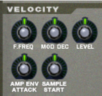
This sets velocity control of the Decay parameter in the Modulation Envelope (see “The Modulation Envelope”).
This sets velocity control of the Attack parameter in the Amplitude Envelope (see “The Amplitude Envelope”).
This sets velocity control of the Sample Start parameter (see “Sample Start and End”), so that it will be offset forwards or backwards, according to how hard or soft you play.
|
•
|
|
•
|
|
•
|
|
•
|
|
•
|
|
•
|
|
•
|
|
•
|
|
•
|
|
•
|
|
|
|
•
|
|
•
|
|
•
|
|
•
|
|
•
|
|
•
|
|
•
|
|
•
|
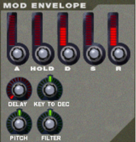
This works just like the Decay parameter, with the exception that it determines the time it takes for the value to fall back to zero after the key is released.
|
•
|
|
•
|
This will make the envelope modulate the pitch, as set in the Pitch section (see “The Pitch section”). Turn the knob to the right to raise the pitch and to the left to lower the pitch. In the middle position, pitch will not be affected by the envelope.
|
•
|
This will make the envelope modulate the cutoff frequency of the Filter (see “The Filter section”). Turn the knob to the right to increase the frequency and to the left to lower the frequency. In the middle position, the envelope will have no effect on the cutoff frequency.
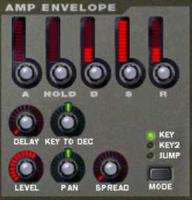
Most of the Amplitude Envelope parameters are identical to those of the Modulation Envelope. So for a detailed description of the following parameters, please refer to the modulation envelope section in “The Modulation Envelope”:
|
•
|
|
•
|
|
•
|
|
•
|
|
•
|
|
•
|
|
•
|
|
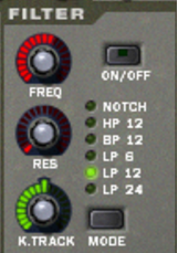
| Mode
|
|
|
•
|
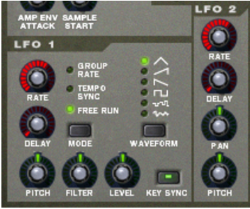
NN-XT features two Low Frequency Oscillators - LFO 1 and LFO 2. “Normal” oscillators generate a waveform and a frequency, and produce sound. Low frequency Oscillators on the other hand, also generate a waveform and a frequency, but there are two major differences:
In this mode, the LFO will run at the rate set for its group in the group section, rather than at the rate set here (see “Group parameters”). This way, all zones in the group will have the exact same modulation rate.
|
•
|
|
| Waveform
|
|
|
•
|
|
•
|
|
•
|
|
•
|
|
•
|