Delay Compensation : How the Delay Compensation works

How the Delay Compensation works
Delay Compensation in individual mixer channels
As soon as you add an effect device/plugin as Insert FX in a Mix Channel or Audio Track device - or in the Master Section device - the sum of the reported inherent latencies of the effect devices in that channel is displayed (in samples) at the bottom of the Insert FX section on the corresponding channel strip in the main mixer. If you add more effect devices in an Insert FX chain, the latency figures are added and summed to a total latency value, which is then displayed in the respective Insert FX sections:
Latency values (in samples) displayed in the Insert FX sections on the main mixer channel strips.
*
What Reason then does to compensate for the inherent latencies in effect devices is to automatically add “invisible delays” to the signals of the other mixer channels. The goal for the delay compensation is to have all mixer channel signals arriving at exactly the same time to the Master Section of the main mixer.
In the picture below, four mixer channels with different Insert FX devices are routed to the Master Section of the main mixer. Reason checks which mixer channel has the longest combined inherent latency, by summing the effect device’s reported latencies individually for each channel.
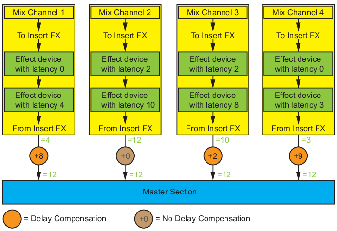
Delay compensation principle for a number of mixer channels routed to the Master Section of the main mixer.
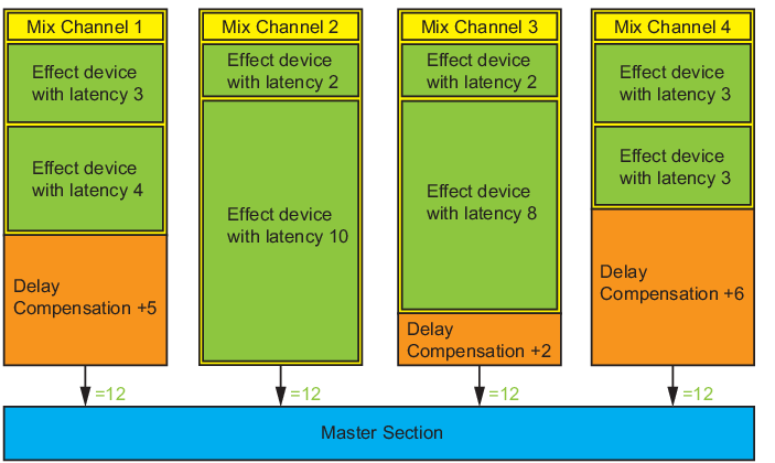
Mix Channel 2 has the longest inherent latency in the example above: 2+10=12 samples. The goal now is to add internal “invisible delays” to the signals from the other mixer channels so that the total delay for each channel is 12 samples.
This means that for Mix Channel 1 Reason automatically adds a compensation delay of 8 samples (to add up to ‘12’). Mix Channel 2, which has the longest inherent latency, doesn’t get any delay compensation at all. Mix Channel 3 gets a delay compensation of 2 samples (to add up to ‘12’) and Mix Channel 4 gets a a delay compensation of 9 samples (to add up to ‘12’).
Now, the signals from all Mix Channels have a total delay of 12 samples and are thus perfectly “in sync” with each other when they reach the Master Section.
If you add more effect devices to any of the Mix Channels, the inherent latencies might become longer, and the delay compensation values are automatically recalculated and adjusted.
A more “graphical” way of looking at the delay compensation is shown in the picture below. Here the inherent latencies of the mixer channels and the delay compensation are represented by proportionally sized boxes, which could make it easier to understand the principle:
Delay compensation principle for a number of mixer channels routed to the Master Section of the main mixer.
As you can see in the picture above Mix Channel 2 doesn’t get any delay compensation, since it has the longest inherent latency of the four channels.
Manually adjusting the latency values
There might be situations where you want to manually adjust the latency values. This could be, for example, if effect devices should report the wrong latency values and thus cause the audio to sound out of phase or weird in other ways.
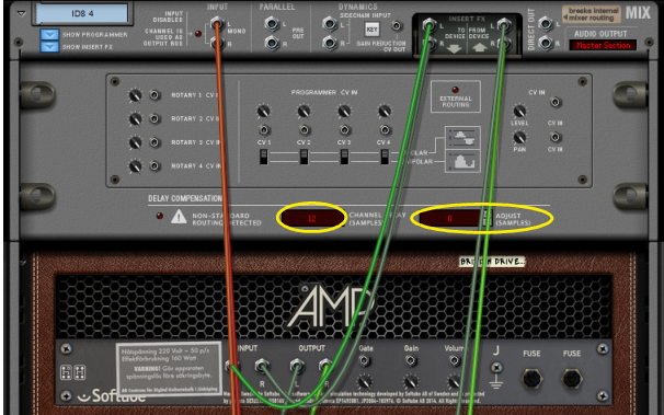
On the rear panel of the Audio Track device’s and Mix Channel device’s Programmer section are two displays: the display to the left shows the total inherent latency for the channel (the sum of the reported inherent latencies of the effect devices in the signal chain), and the display to the right shows the number of samples you might have manually adjusted the latency value:
*
The sum of the reported inherent latencies (Channel Delay) and any manual adjustment is displayed in the respective Insert FX sections on the main mixer channel strips:
The “Total signal path latency” figure displayed on the Transport panel is the sum of the individual channel which has the longest inherent latency, plus the inherent latency of the Master Inserts effect devices:
*
Delay Compensation with Busses and Parallel Channels
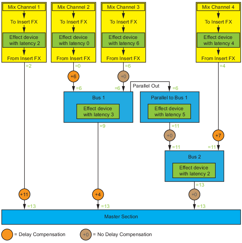
When using Parallel Channels and Output Busses the same principles apply, i.e. the total latencies for all mixer channels and busses should be the same when the signals reach the Master Section. Also, the latencies of the signals entering the same Output Bus must also be the same, to avoid phasing problems etc. In the picture below, a number of mixer channels, parallel channels and busses are used:
Delay compensation when using Parallel Channels and Busses.
As you can see in the picture above, the signal chain with the longest inherent combined latency is: Mix Channel 3 > Bus 1 > Parallel Bus 1 > Bus 2 > Master Section; this signal chain is therefore not delay-compensated. All other signals are delay-compensated where necessary, which is indicated by the orange circles in the picture.
Delay Compensation to Send FX busses
Since each mixer channel is delay-compensated individually, we need to make sure that any signals from the mixer channels to the Send FX busses reaches the Send FX busses at the same time. To make the signals to each of the Send FX busses come “in sync”, there is also a built-in delay compensation to the eight FX sends of each mixer channel.
About Send FX Returns
Reason doesn't compensate for any inherent delays in the Send Effect devices themselves, as this would make the delay compensation scheme extremely complex. Also, Send FX are traditionally often used for delays and reverbs, where a little extra inherent delay won't matter much.
*
About the Master Insert FX
Reason considers all audio signals to pass through the Master Section in the main mixer; this is where all signals eventually should end up in sync. But the Master Section has an Insert FX section too, and effect devices used here can often have a significant inherent latency (maximizers, mastering EQs etc). However, since all signals pass through these effect devices in sync, no delay compensation is performed on the Master Insert FX devices. This is why the Master Section device in the rack lacks Channel Delay and Adjustment displays.
Problematic configurations
The examples below describe a number of “problematic” routings and how Reason handles these regarding delay compensation.
When non-standard routings are detected, the red LED in the Delay Compensation section of the back of the Mix Channel/Audio Track device Programmer section lights up. Hovering over the LED brings up a tool tip, which describes the detected type of problem;
Parallel signal paths within the channel
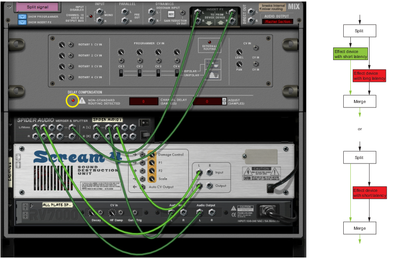
In these types of configurations Reason uses delay compensation only for the shortest signal path, i.e. the signal path that has the shortest inherent latency between the To Device and From Device connections:
Example of a parallel signal configuration where only the delay for the shortest path is used for delay compensation.
Sub-mixers with Send FX routings within the channel
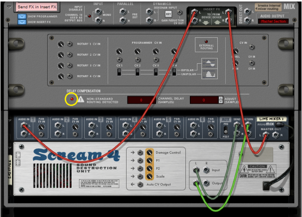
In these types of configurations Reason uses delay compensation only for the shortest signal path, i.e. the signal path that has the shortest inherent latency between the To Device and From Device connections. If there are send effects in the path, this means that the inherent latency will be the same, or longer with these effects. Therefore, send effects are always disregarded from any delay compensation:
Example of an internal “send fx” routing inside an Insert FX configuration.
Loopback within the channel
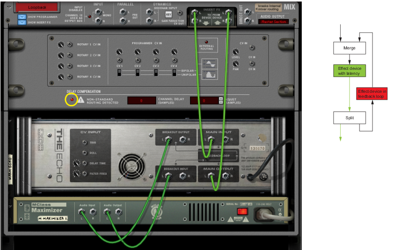
In these types of configurations Reason uses Delay compensation only for the shortest signal path, i.e. the signal path that has the shortest inherent latency between the To Device and From Device connections. If there are any feedback connections in the signal path, these will be disregarded from any delay compensation:
Example of a feedback loop, which is disregarded from delay compensation.
External routing from the channel
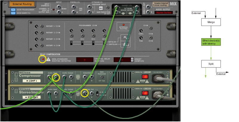
If there are any connections to devices outside the Insert FX section, and these devices are routed to other mix channels (or to the Master Section), any inherent latencies in the external effect devices will be disregarded from any delay compensation:
Example of an external routing from (any of) the Insert FX devices.
Broken signal path in the channel
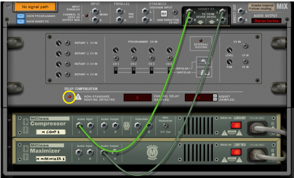
If the effects signal path should be broken in the channel, the tool tip “Could not calculate latency. The default value of 0 samples was used” is displayed. This means that the program couldn't follow the signal path, which may be because it's not completely connected, for example:
Example of a broken signal path in a channel.
About using the Direct Out connections of the mixer channels
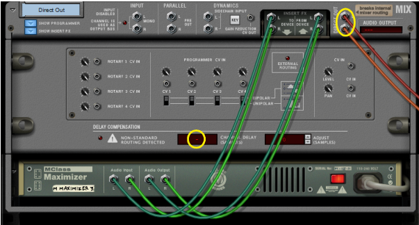
Since connecting the Direct Outs of a Mix Channel or Audio Track device automatically disconnects it from the Master Section of the main mixer, any delay compensation is also automatically disabled. This is indicated by “ - “ in the Channel Delay display:
Example of when the Direct Outs are used in a channel.
About the Metronome Click
Reason adds the Metronome Click (if selected) at the Hardware Interface (after the Master Section). This means that if there's a delay in the signal path, the Metronome would be heard before the rest of the audio on playback. Therefore, Reason uses delay compensation also for the Metronome so it always plays back correctly in sync.
Recording with Delay Compensation
When you record audio using External Monitoring (Preferences - the Audio tab), Reason repositions the audio according to the reported audio card latency. Recorded audio is positioned earlier on the track, by Input Latency + Output Latency. When delay compensation is active, the total delay time is then added to the audio repositioning.
Playing and monitoring with Delay Compensation
A problem with delay-based delay compensation is that all signal paths are delayed equally. Even if you have no Insert FXs in the signal path for your track, it might be delay-compensated (depending on what’s in the rest of the channels in the mixer). This could make it hard to play instrument devices and monitor through Reason. Some good advice could be to:
*
*
About bouncing mixer channels
Delay compensation is taken into account when you bounce mixer channels - both to files on disk and to new tracks in the song - as well as when you use the “Bounce in Place” function.

Delay Compensation : How the Delay Compensation works