SynchronousTimed Effect Modulator : Using Synchronous

Using Synchronous
Loading and saving patches
Loading and saving patches is done in the same way as with any other internal Reason device, see “Loading patches” and “Saving patches” for details.
Drawing and assigning modulation curves - a tutorial
To describe the basic principles with modulation curves, let’s have a look at an example of how you can design a modulation curve and then have it modulate a couple of effect parameters:
1.
A Dr Octo Rex device is created and the default Rex loops are loaded in the device.
2.
The audio outputs of the Dr Octo Rex device are automatically connected to the audio inputs of the Synchronous device. The audio outputs of the Synchronous device are also automatically routed to the Dr Octo Rex’s Mix Channel.
3.
All parameters in the Synchronous device are now reset to their default values. The yellow modulation curve is automatically selected and reset to a straight line down in the display.
4.
The default Rex loop in the Dr Octo Rex device starts to play back and the Position Indicator at the top of the Synchronous display starts to advance in sync with the sequencer.
The Position Indicator advances in sync with the sequencer tempo.
5.
6.
7.
8.
9.
A sawtooth wave is now visible in the display. The rate of the sawtooth wave is 1/8th of a bar, since you selected this when you clicked the 1/8 button. The amplitude of the sawtooth wave is increased or decreased according to your vertical drawing direction.
10.
The Rate buttons have now disappeared from the panel, since they are of no importance when you use the Line tools.
11.
Alter the amplitude (y-axis positions) as you draw.
12.
Now, you have half a bar of a 1/8th sawtooth waves and one and a half bars of a stepped “free hand” curve:
Now, let’s assign the yellow modulation curve to the effect parameters to be modulated. In this example we will assign the curve to the Freq and Resonance parameters of the Filter section:
1.
2.
3.
Yellow modulation amount semicircles appear around the Freq Modulation knob and around the Resonance Modulation knob, to indicate the modulation amounts and their “directions” (positive or negative modulation):
Setting the modulation amounts.
4.
Congratulations, you have now created your first looped Filter modulation in Synchronous!
Editing modulation curves - a tutorial
Basically, there is one way you can edit an existing Modulation Curve: by redrawing the part of the curve you want to change. The examples below describe two basic use cases.
Changing an existing curve’s amplitude
If you want to adjust the modulation curve’s amplitude anywhere throughout the modulation loop, proceed as follows:
1.
The curve is highlighted in the display.
2.
If the curve is a waveform, make sure you also click the correct Rate button.
3.
*
The amplitude starts at the level where you placed the mouse pointer and ends at the level where you released the mouse button. The level change between the start and end point is linear.
*
The amplitude starts at the level where you placed the mouse pointer, then follows your drawing directions, and ends at the level where you released the mouse button. The levels changes are now individual between each vertical grid line.
*
*
Replacing a part of a curve with another one
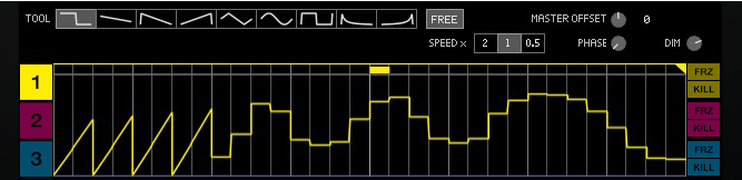
To replace the current modulation curve with a different curve anywhere in the modulation loop, use the same principle as described above in “Changing an existing curve’s amplitude”. The only exception here is that you now freely choose the new curve shape, regardless of the existing curve shape. You can replace an existing curve in as many places throughout the loop as you like.
*
*

SynchronousTimed Effect Modulator : Using Synchronous