SynchronousTimed Effect Modulator : Panel reference

Panel reference
The display section
Tool buttons and the Free button
*
The result when you draw will be a jagged curve with vertical steps.
*
*
In these situations, the Rate buttons define the waveform cycle lengths, see “Rate buttons”.
*
*
Rate buttons
*
You can alter between different time rates throughout the loop by clicking another Rate button and continue drawing from where you stopped.
*
Speed control
*
The Speed can be set to 2, 1 or 0.5 times the main sequencer tempo, and are set individually for each of the three modulation curves. The speeds are indicated by the Position Indicators’ advancement when the main sequencer is running.
The vertical grid lines in the display represent 1/16th note.
The vertical grid lines in the display now represent 1/8th note.
The vertical grid lines in the display now represent 1/32th note.
Phase knob
*
Range: 0-360 degrees.
The phase is changed individually for each curve type (waveform) used in the loop. The picture below shows the same modulation curve with a Phase setting of 0 and ~180 degrees, respectively:
The same modulation curve at 0 degrees (top) and 180 degrees (bottom) Phase values.
As you can see in the picture above the first part of the curve, which is a sinewave with a 1/4th note rate is phase shifted 180 degrees. The second part, which is a stepped line, is not changed at all. The third part of the curve, which is a sawtooth wave with a 1/8th note rate is also phase shifted 180 degrees. However, since the third part has a 1/8th note rate, the actual “distance” it has been moved is half as long as the 1/4th note rate sinewave in the first part of the curve. This is because all waveform curves are phase shifted individually throughout the modulation curve.
*
*
Master Offset knob
*
This determines where in the modulation loop the playback should begin. Negative Master Offset values moves the playback start position backwards, and vice versa.
*
Range: +/- 32 16th notes (in Speed x 1 mode).
Range: +/- 32 8th notes (in Speed x 0.5 mode).
Range: +/- 32 32th notes (in Speed x 2 mode).
Dim knob
*
At zero, all modulation curves are equally bright all the time.
At maximum level, only the selected modulation curve is visible in the display.
*
Curve Select buttons
*
Setting the loop lengths
The three modulation curves can have their own individual loop lengths. The loop length for a modulation curve can be adjusted, simply by repositioning its loop locator:
1.
2.
Setting the loop length for the yellow modulation curve.
3.
The loop locator will snap to the closest leftmost vertical grid line in the display. In Normal speed, this means it will snap to a 1/16th note grid.
*
FRZ (freeze) buttons
1.
2.
The playback automatically continues at the position in the loop where it should have been if the freeze function had not been activated.
Kill buttons
1.
The modulation curve is preserved but does not modulate any parameter as long as the Kill function is active. Also, the killed curve becomes invisible in the display.
2.
The modulation curve is activated and automatically continues with the modulation at the current position in the loop.
Modulation controls
The Modulation Control knobs are used for setting a modulation amount (positive or negative) for the effect parameter right below each Modulation Control knob. To set up a modulation, proceed as follows:
1.
All assignable Modulation Control knobs are automatically colored according to the selected modulation curve:
2.
Setting the modulation amount.
A colored semicircle appears around the Modulation Control knob. The semicircle shows how much the selected modulation curve affects the corresponding effect parameter (below each Modulation Control knob) - and in which direction (positive or negative).
*
3.
All Modulation Control knobs can be modulated by all three modulation curves at the same time if you like. The modulation amounts and directions can be set independently for each modulation curve. The picture below shows a Modulation Control knob which is affected differently by all three modulation curves:
Different modulation amounts set for each of the three modulation curves.
Dist section
Amount knob
*
At 0, the signal is left unaffected.
Character knob
*
The effect varies depending on the selected distortion type (see below).
Distortion type selector
*
In Ring Mod mode, the Character knob controls the ring modulator frequency.
In Lo-Fi mode, the Character knob controls the sample rate. There is no anti-aliasing filter in this algorithm, so there will be a lot of nice lo-fi character to the sound.
Post Filter button
*
The routing order can have a big impact on the frequency content in the sound. Since the Dist section adds frequencies to the sound, you might want to preserve these by routing the Dist section after (Post) the Filter section.
Dist On/Off button
*
If switched off, the signal is bypassed unaffected.
Filter
Freq knob
*
Resonance knob
*
Filter Type switch
*
The filter types are:
Lag knob
*
This works like a sort of “portamento” for the Freq parameter, i.e. the Freq parameter will move more slowly when modulated if the Lag value is high.
Filter On/Off button
*
If switched off, the signal is bypassed from the Filter section.
Delay
Amount knob
*
At 0, the signal is left completely dry.
Time knob
*
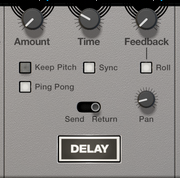
If the “Sync button” is on, the Time values can be stepped between time divisions (e.g. 1/1, 1/2,
1/4, 1/8 etc.) relative to the main sequencer tempo.
Feedback knob
*
Keep Pitch button
When you manually change the Rate during recording or playback, you will notice that the pitch of the delayed signal also changes. If this effect is undesirable, you can enable Keep Pitch, which will ensure that the pitch remains fixed regardless of changes in Rate.
Ping Pong button
With Ping Pong enabled, the stereo position of each delay repeat will alternate between left and right. The “Pan knob” determines the stereo width as well as the position of the initial repeat. When the Pan knob is set to full Left, the first delay bounce will be panned hard Left, the second will be panned hard Right, and so on. When the knob is set to full Right, the order is reversed (R > L > R etc).
Sync button
*
Set the time divisions (e.g. 1/1, 1/2, 1/4, 1/8 etc.) with the “Time knob”.
Roll button
The Roll function works like a “freezed” delay, perfect for stutter, repeat and glitch effects. When the Roll button is on, and you turn up the Feedback knob, the input signal to the Delay section is gradually suppressed, while the feedback is automatically raised internally. In Roll mode, the Amount knob controls the level of the delay signal when the Feedback parameter is turned up. When the Feedback is set to zero, the Amount value is disregarded.
1.
2.
*
*
Pan knob
*
Send/Return switch
*
The picture below shows the different configurations schematically:
The schematic placement of the Amount knob in Send and Return mode, respectively.
Delay On/Off button
*
If switched off, the signal is bypassed from the Delay section.
Reverb
Amount knob
*
Decay knob
*
Size knob
*
Lowering this parameter results in a closer and gradually more “canned” sound. Raising the parameter results in a more spacey sound, with longer pre-delay.
Damp knob
*
Raising the Damp value cuts off the high frequencies of the reverb, thereby creating a smoother, warmer effect.
Send/Return switch
*
The picture below shows the different configurations schematically:
The schematic placement of the Amount knob in Send and Return mode, respectively.
*
Reverb On/Off button
*
If switched off, the signal is bypassed from the Reverb section.
Level
Level knob
*
Range: - INF to + 12 dB.
*
In & Out switch
*
Master Controls
Dry/Wet
*
At 0 the effects are completely bypassed and the input signal is passed through Synchronous unaffected.
Master Level
*
Range: - INF to + 12 dB.

SynchronousTimed Effect Modulator : Panel reference