The Main Mixer : The channel strip

The channel strip
The channel strip is divided into sections, each marked with a section header. Mix Channel and Audio Track channel strips have identical parameters. Here is a detailed rundown of the parameters and functions in each section.
Input section
Input Gain
Signal Path section
The Dynamics, EQ and Insert effect sections will by default process a channel signal in that order, i.e. the order of the sections as shown in the channel strip (from the top down). By using the buttons in this section, the signal path order can be changed internally.
Dynamics section
Each channel strip has a powerful dynamics section featuring compression/limiting and gating/expansion. The upper part of the section (with a white background) is the compressor/limiter, and the lower part (gray background) is the gate/expander. The compressor and gate processing can be independently switched in or out of the circuit.
Compressor/Limiter
Compressors reduce dynamic range by evening out the difference between loud and quiet signals. This makes signal levels easier to balance, and can add punch and sustain to the sound.
The Main Mixer’s compressor/limiter is a flexible processor which has soft-knee (a gradual, smooth onset of compression) characteristics but can be switched to peak limiting, where levels above the set threshold are instantly reduced. The compressor also features automatic make-up gain.
The parameters are as follows:
Gate/Expander
Gating or expansion will attenuate signals below a set threshold; the opposite of compression. It can be used to reduce or eliminate unwanted background noise that may be present when there is no signal to mask it. Gating is also commonly used to reduce microphone “bleeding”, e.g. when recording a close-mic’ed drum kit you can use gating to silence the tom microphones when the toms aren’t being played to tighten up the sound, and for special effects like “keying” (see below).
Higher expansion ratios (10:1 and above) are referred to as noise gating, where the channel is completely silenced if the level drops below the set threshold.
The Gate/expander has the following parameters:
About the Filters To Dynamics Sidechain button
When this button (found in both the Input and EQ sections) is activated, the Low Pass and High Pass filters can be used to filter the channel sidechain signal before the dynamic processing.
The channel signal itself will not be directly affected by the filters, only the sidechain signal. The filtered sidechain signal is what triggers the dynamic processing, but the dynamic processing is applied to the channel signal. This allows you to use frequency sensitive compression.
By trimming low and/or high frequencies you can specify which frequency range should trigger the compressor or gate. A typical application of frequency sensitive compression is “de-essing” where harsh sibilants in vocal material are reduced or eliminated. This is done by filtering the Sidechain signal so that only high frequencies (“s” noises) will trigger the compressor.
*
The Key button and the Dynamics Sidechain inputs
You can use external signals to trigger the Dynamics section. This is done by connecting an external signal output to the Sidechain inputs on the back of the Mix Channel or Audio Track rack device.
The Sidechain inputs.
When a cable is connected to the Sidechain inputs the “KEY” button is activated automatically and the Dynamics section for the channel will now be “keyed” i.e. triggered by the external signal instead of the channel signal.
For example, you could use a drum loop to trigger the gate for a channel playing a synth pad to create rhythmic chord effects.
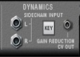
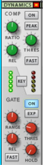
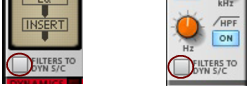
See “Using compression sidechaining” for a description of further uses of sidechaining.
About Gain Reduction CV
The Gain Reduction CV out connector on the back of a Mix Channel or Audio Track rack device can be used to modulate other parameters with the amount of gain reduction applied by the compressor/gate. The gain reduction CV out can be used as an envelope follower as the CV follows the dynamics of the original signal.
For example, try using gain reduction CV to control filter frequency for “auto-wah” effects.
EQ section
This is a four-band EQ with parametric midrange controls and high and low frequency shelving bands. The EQ can be switched between two operating modes, each with slightly different curve characteristics. There is also a filter section with low pass and high pass filters.
The EQ can be placed before or after Dynamics in the signal path - see “Signal Path section”.
The parameters are as follows:
The Spectrum EQ Window
The EQ section can also be displayed and edited “visually”. This is done in the Spectrum EQ floating window. Besides the EQ functionality, the Spectrum EQ also features a spectrum analyzer which displays the audio frequency content of the selected mixer channel in real-time. Here is how you can work with the Spectrum EQ:
1.
The Spectrum EQ window shows up and the (pre-Fader) frequency content of the currently selected mixer channel is displayed in gray during playback:
The Spectrum EQ Window with audio playing back.
*
*
*
*
2.
You can also activate the HPF and LPF Filters, E Mode, HF Bell mode and LF Bell mode for the selected mixer channel by ticking the corresponding check boxes in the window. The pictures below shows how the different objects in the Spectrum EQ window correspond to the channel strip parameters:
The Spectrum EQ Window with the Filters, EQ, E Mode, Bell Mode and Analyzer functions active during audio playback.
The Spectrum EQ editing objects (points) and what parameter(s) they affect in the mixer channel strip.
*
Dragging sideways changes the frequency value and dragging vertically changes the gain (of the EQ points). As you edit the points, the corresponding channel strip parameter(s) are updated in real-time - and vice versa. The white line in the window shows the resulting EQ (and Filter, if activated) curve.
This allows you to change either frequency or gain without affecting the other.
*
(The point remains selected until you touch another point with the mouse or click on the window background.)
The HMF EQ point is selected and highlighted in the window.
*
*
This is only valid for the HMF and LMF EQ points, since these are the only ones that have a Q parameter.
*
Insert FX section
The channel strip Insert FX section allows you to load an Effect Combi patch, which can in turn contain any number of effects and other devices. Insert effect devices that belong to the patch are added to the Audio Track or Mix Channel device in the rack.
The main parts of this section are the assignable Rotary knobs and buttons. Combinator Effect patches in the Factory Sound Bank will have various parameters and switches assigned to these controls, and the labels will have names describing the parameter/function.
Insert effects process the whole channel signal, as opposed to Send effects where the effect balance is adjustable. Typical examples of when to use insert effects include compression, distortion and modulation effects such as chorus.
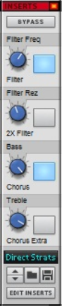
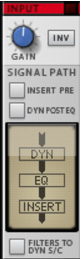
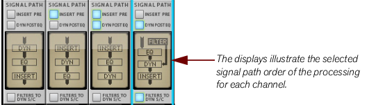
The Insert effects can be placed ahead of the Dynamics and EQ sections in the signal path - see “Signal Path section”.
*
Insert effects patches in Combinator format can be loaded.
See “Insert FX” for descriptions of how to work with Insert effects.
The Insert FX section in the channel strip contains the following parameters:
FX Sends section
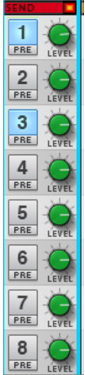
Send effects, which are global for all channels in the Main Mixer, are connected to the Master Section rack device. Up to 8 Send effects can be used simultaneously. For a description of how to use Send effects, see “Send FX”.
The FX Sends section contains the following parameters:
Fader section
The Fader section is used for controlling the level of the channel and its stereo placement in the mix. The section has the following parameters:
If you are using Output Busses (see “Output Busses”) and/or Parallel Channels (see “Parallel Channels”), the Solo and Mute functions affect the other concerned channels in an intelligent way, see “Solo, Mute and Send FX logic”.
If a channel is an Output Bus (see “Output Busses”), the Fader section background is colored and the Fader knob is red.
About Level/Pan CV
On the back of the Programmer section of a Mix Channel or Audio Track device you will find CV inputs for the channel Level and Pan controls. These allow for automatic level and pan control from sources that output CV signals.
*
Changing Fader section parameters on multiple channels simultaneously
In the Fader section you can change parameter values in a “ganged” or “linked” fashion on several selected Mix Channels. You can change the Mute, Solo and Level fader parameters this way. The example below shows seven selected channels, where the Level is reduced on the KorgBass channel and the rest of the channels’ Faders follow along (with the same amount of level change in dB for each channel):
*
Channel Header section
The Channel Header is always visible at the bottom of the channel strip. It contains the following items:
The Edit Focus indicator - When you select a channel, the horizontal strip at the top of the Channel Header lights up red to indicate Edit Focus. The channel most recently clicked will have edit focus, regardless of how many channels are selected. When using [Ctrl](Win)-click or [Cmd](Mac)-click to deselect previously selected channels, edit focus will be on the most recently deselected channel.
Edit Focus also reflects the last selected track or Mix device, which is useful when moving between work areas because the channel with Edit Focus will always be in view in the Main Mixer. For example, if you select an ID8 track in the sequencer, the Mix channel to which it is connected will be scrolled into view in the Mixer, and will be given Edit Focus.
The top strip is lit to indicate Edit Focus.
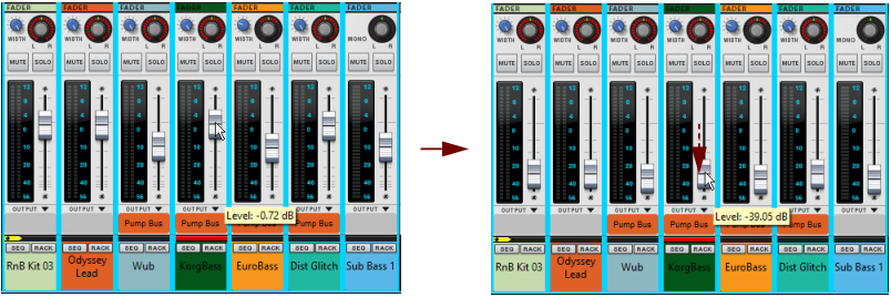
The Remote Base Channel indicator - To the left in the same horizontal strip area a small yellow arrow symbol can be shown. This is the Remote Base Channel indicator, which shows which channel is considered the first or base channel when using Remote Control - see “Setting the Remote Base Channel”.
The Remote Base indicator.
The RACK and SEQ buttons allow you to switch to a channel’s rack device or sequencer track directly from the mixer - see “Switching between channels, rack devices and tracks”.
The Channel Header area reflects the selected Track Color (see “Coloring mixer channels”).
You can rename the channel by double-clicking on the name (see “Naming mixer channels”).
Note that the Channel Header is a little shorter if the channel is a Parallel Channel (see “Parallel Channels”).

The Main Mixer : The channel strip