The Main Mixer : The Master Section strip

The Master Section strip
The Master Section is where all your audio track and mix channels are mixed down to the Master Out bus. The Master Section strip contains a bus compressor and Insert FX section, both of which process the master bus, as well as send/return master level and pan controls for the eight FX Sends. Any processing applied to the master bus affects all channels that are routed to the Master Section.
Master Compressor section
The Master Compressor is perfect for providing the final “fairy dust” to your mix. It can add punch and cohesion, and generally make the mix sound bigger and more powerful. The compressor is very straightforward in operation and features make-up gain as well as program-adaptive Release.
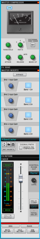
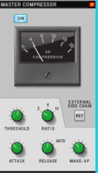
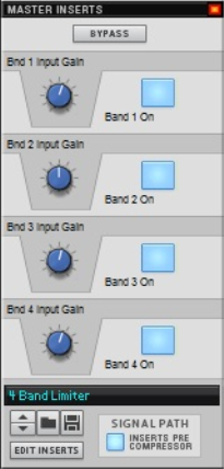
The Master Compressor can be applied pre or post Master Insert section - see “Master Inserts section”.
The parameters are as follows:
See “Using compression sidechaining” for a description of how sidechaining can be used.
FX Send section
This section controls the master levels of the FX Sends. Send effect devices are connected to the Master Section via the eight FX Send and eight FX Return connectors on the back of the rack device.
See “Send FX” for a description of how to set up an use Send FX.
The Send bus can be monitored via the Control Room output - see “Control Room output section”.
The section contains the following items:
Master Inserts section
The Master Inserts Section is identical to the Insert FX section in the channel strips, except that it affects the master bus, i.e. the whole mix. You can load Combinator effect patches, which can include anything from a single device to a complex array of multiple devices, to process the master bus.
The Master Insert slot is ideally used to apply mastering effects for finalizing the mix.
Devices that belong to the Insert effect patch are added to the Master Section device in the rack.
The main parts of this section are the assignable rotary knobs and buttons. Combinator Effect patches in the Factory Sound Bank will have various parameters and switches assigned to these controls, and each label will have a name describing the assigned parameter/function.
The Master Insert effects can be placed ahead of the Master Compressor in the signal path. By default, the Master Insert effects are placed after the Master Compressor in the signal path. This makes sense, as you usually add a Maximizer or Mastering Combi patch as a Master Insert effect, and this must be last in the signal path to avoid clipping on the output. However, if necessary, you can place the Master Insert effects before the Master Compressor, by activating the "Inserts Pre Compressor" button.
*
Insert effects in Combinator format can be loaded.
See “Insert FX” for descriptions of how to work with Insert effects.
The Inserts section in the Master Section contains the following parameters:
FX Return section
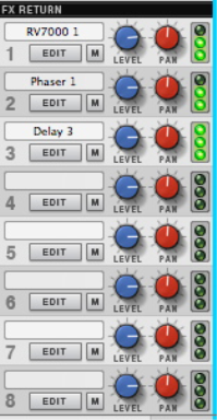
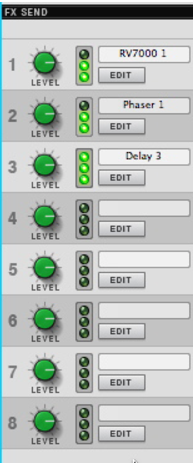
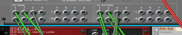
This section controls the master levels of the FX Returns. Send effect devices are connected to the Master Section via the eight FX Send and eight FX Return connectors on the Master Section device. See “Send FX” for a description of Send FX.
Send/Return connectors on the Master Section device.
You can monitor the Return bus via the Control Room output - see “Control Room output section”.
The section contains the following items:
Master Fader section
The Master Fader controls the final output level of the mix to be recorded or exported to a file. It should normally be set to 0dB. The Master Fader should never be used to adjust the monitoring level - this is what the Control Room bus is for (see below).
The section contains the following items:
Spectrum EQ (Spectrum Analyzer) Window button
Below the Meter is a button for bringing up the Spectrum EQ Window. Since there are no Filter or EQ sections in the Master Section, the Spectrum EQ Window is used only for displaying the frequency content of the Master Section.
Control Room output section
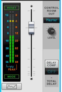
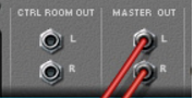
The Control Room outputs are located on the back of the Master Section device. To use the Control Room output section, the outputs have to be connected to your monitor system. This can be done by manually patching cables from the “Ctrl Room Out” connectors to a separate output pair on the Reason Hardware Device - see “Manual audio routing”.
The Control Room outputs, which are separate from the Master Out bus, are the outputs that you should monitor (listen) from. This allows you to monitor the main mix and to adjust your monitoring level without affecting the Master Out bus. You can also monitor the FX Send or Return buses in this section.
The section contains the following items:
Delay Comp
*
The total delay of the Main Mixer signal (at the Master Out) is displayed below the display. See the “Delay Compensation” chapter for more information about delay compensation in Reason.
Master Section Header
The Header is always visible at the bottom of the Master Section. It contains the following items:

The Main Mixer : The Master Section strip