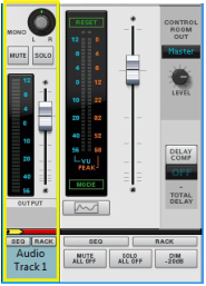
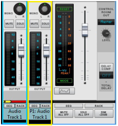
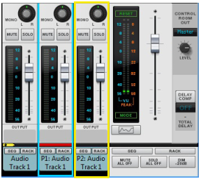
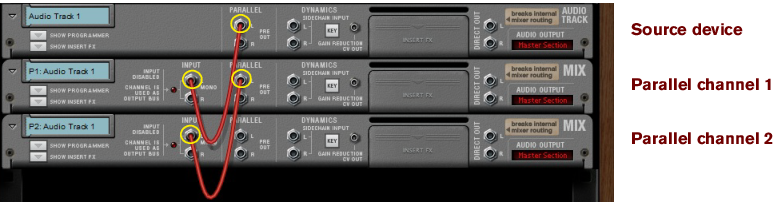
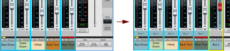
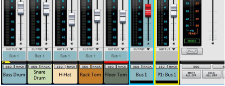
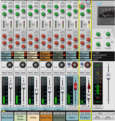
Parallel Channels A very flexible way of working with insert effects is to use parallel channels that host the effects, while keeping the dry signal of the source channel intact. This way you can freely control the levels of the dry signal and the separate effects - and also control the sound of each effect individually from each of the parallel channels. You could, for example, have one parallel channel with a compressed distortion effect, another parallel channel with a Delay, and so on. Then, you can freely EQ the effects in each of the parallel channels, as well as control their levels individually from each Fader. Creating Parallel Channels Parallel channels can be created as follows: 1. Select the source Mix/Audio Track channel strip in the Main Mixer, or its device in the rack. 2. Select “Create Parallel Channel” from the Edit menu or context menu. A new Mix Channel is created and placed to the right of your original channel in the Main Mixer: A Parallel Channel created for Audio Track 1. The parallel Mix Channel is automatically named “P1: <source channel name>” and its channel header is colored according to the source mixer channel header. Both the source channel and the parallel channel also get shorter channel headers to indicate they are routed in a parallel configuration. If you want to add more parallel channels to your source channel, select the last created parallel channel and select “Create Parallel Channel” from the Edit menu or context menu. This adds another parallel channel to your source channel: Another Parallel Channel created for Audio Track 1. In the rack, the Parallel out jack(s) of the source Mix Channel/Audio Track device are automatically connected to the Direct Input jack(s) of the first parallel Mix Channel. The second parallel Mix Channel is then connected to the first parallel Mix Channel, and so on: Parallel Channels 1 and 2 for the Audio Track 1 source channel in the rack. Since the Audio Track/Mix Channel device only has one pair of Parallel out jacks, any additional parallel channels have to be created from the last created parallel channel. If your original channel is in mono, only the left parallel output is connected to the left input of the parallel channel. 3. Now, you can create Insert FX in each of the parallel channels and process the signal of your source channel separately, in parallel. It might also be a good idea to create a separate Output Bus for the source channel and all parallel channels, see “Creating an Output Bus”. Creating a Parallel Output Bus Parallel channels can also be created for Output Bus channels, for parallel processing of the entire Bus signal. The following example shows a drum kit, with a channel for each drum, that we want to assign to an Output Bus and apply parallel compression to: 1. [Shift]-select all drum channels in the mixer. 2. Press [Ctrl]+[G](Win) or [Cmd]+[G](Mac) to create a new Output Bus to automatically route the drum channels to. A new Output Bus channel, named “Bus 1”, is created to the right and the selected channels are automatically routed to it as indicated on the channels’ Output labels. 3. Select the “Bus 1” channel in the mixer and select “Create Parallel Channel” from the Edit menu or context menu. A parallel channel, the “P1: Bus 1” is created and the “Bus 1” Output Bus channel is automatically connected to it. 4. Activate the Compressor in the “P1: Bus 1” parallel channel and raise the Compression Ratio up high. 5. Raise the Level fader on the “P1: Bus 1” channel to gradually introduce the heavily compressed sound (in parallel with the dry signal of the “Bus 1” channel). Deleting Parallel Channels To delete a Parallel Channel, select its mixer channel strip - or its device in the rack - and press [Delete] or [Backspace]. Confirm the deletion in the alert that appears. Naming Parallel Channels When you create a Parallel Channel it is automatically named after its source channel according to: “P1: <source channel name>”, where “P” stands for Parallel and “1” for the first parallel channel. If you add on more parallel channels, the following channels are named “P2: <source channel name>” and so on. If you change the name of the source channel, all the parallel channel are automatically renamed accordingly. You can then manually rename each parallel channel afterwards if you like. To revert to the automatically generated name, double-click the parallel channel’s name, press [Delete] or [Backspace] and then [Enter].