Thor Polysonic Synthesizer : Using the Programmer

Using the Programmer
The Programmer contains the main synth parameters.
*
The Programmer appears below the Controller panel.
*
The Voice section contains the basic synth parameters and the parameters are “per-voice”, i.e. all envelope and LFO cycles are triggered individually for each voice. The Global section to the right contains global parameters that affect all voices.
*
The open Oscillator and Filter slots allow you to select between different types of oscillators and filters.
*
Basic connections - a tutorial
There are certain pre-defined connections available between the Oscillator 1-3 slots and the Mixer, Filter 1/Shaper, Filter 2 and Amp sections. On the panel itself, lines with arrows are shown to indicate the standard signal paths.
*
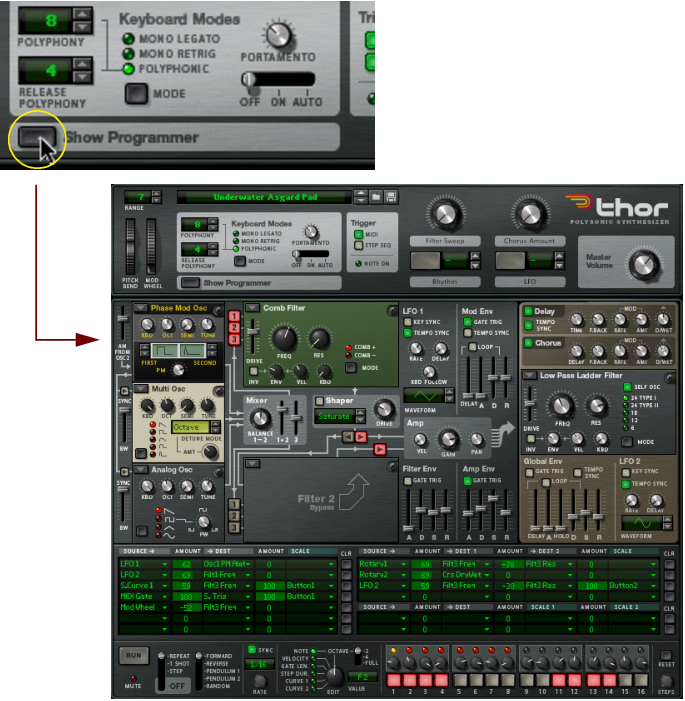
Note that you can also connect sections using the Modulation bus section (see “Modulation bus routing section”). You are not in any way limited to the pre-defined routings, but they do provide a quick and convenient way to connect the basic synth “building blocks” together.
In the following tutorial we will create a standard setup using two oscillators and two filters to demonstrate Thor basics and the (standard) signal path:
1.
The “Init patch” is a basic setup with an Analog oscillator in Oscillator slot 1 and a Ladder LP filter in Filter slot 1 loaded. A connection between Oscillator 1, Filter 1 and the Amp section is already activated, so you get a sound when you play.
Below the Oscillator 1 slot in the upper left corner are two more slots, currently empty. These are the Oscillator 2 and 3 slots, respectively. The three Oscillator slots are basically identical in that they can each be loaded with one of 6 oscillator types.
2.
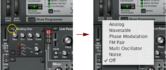
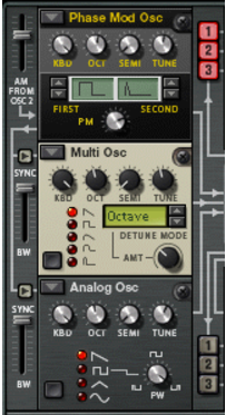
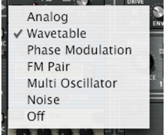
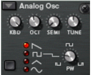
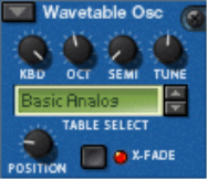
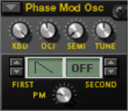
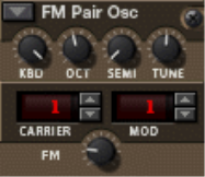
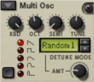
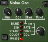
The following oscillator types are available; Analog, Wavetable, Phase Modulation, FM Pair, Multi and Noise. For a description of the various oscillator types, see “The Oscillator section”.
Selecting oscillator type.
With a basic connection setup, the Oscillator outputs are internally connected to the “Mix” section. To pass the output signal onwards in the signal chain, you first have to activate a connection. This is done using the two vertical rows of routing buttons labelled 1, 2 and 3 to the right of the Oscillator section.
All three oscillators can be simultaneously routed to both filters, serially or in parallel (or any combination of these variations). This is explained later in this tutorial.
By activating one or more of these buttons means that the oscillator (1 to 3) is routed to the corresponding Filter. Currently, Oscillator 1 is connected to Filter 1 slot (which is pre-loaded with a Ladder LP filter).
This is indicated by the “1” routing button being lit. The Filter 2 slot is currently not active, which is indicated by a blank panel.
3.
Now if you play a few notes you should hear both Oscillator 1 and Oscillator 2, via the Filter 1 section.
Actually, the Amp section output is routed via the Global section before being sent to the Main Outputs, but as currently nothing is activated in the Global section the signal passes through unprocessed.
4.
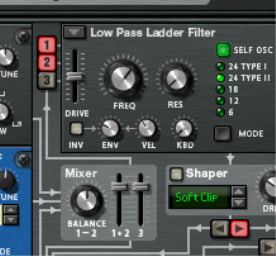
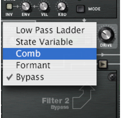
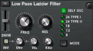
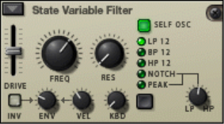
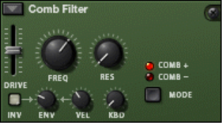
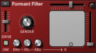
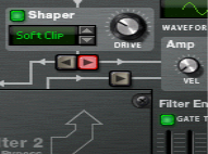
A pop-up menu with the four available Filter types appears. For a description of the filter types, see “Filter slots”.
5.
Now that the Filter 2 slot in the Voice section is active, you can connect the oscillators to it by using the lower row of routing buttons.
6.
Now the two oscillators are connected to Filter 2.
7.
Now if you play a few notes, both oscillators are routed via both filter sections in parallel. You could of course select to pass only one of the oscillators via one filter and both oscillators via the other - any combination is possible.
You can also connect the Filter 1 and 2 sections serially, meaning that the output of Filter 1 is passed through Filter 2 before reaching the Amp section. This is done as follows:
8.
If you leave them on the oscillators will pass through Filter 2 twice; both via Filter 1 and directly. This is also perfectly “allowable”, but to make things clearer in this tutorial we will use a standard serial filter setup.
9.
Now the filters are connected serially, with the output of Filter 1 (via the for now inactive Shaper) being connected to the Filter 2 input. Both oscillators are processed by both filters connected in series.
That concludes this tutorial on how the pre-wired connections in the Voice section can be used, but note that you can also use the Modulation bus to make connections - see “Modulation bus routing section”.
Other pre-defined routing assignments
There are other sections in Thor which are pre-defined and can be used without having to make any prior assignments:
*
The amount of filter envelope control is controllable by using the “Env” parameter in each Filter section.
*
The Oscillator section
Oscillators generate the basic raw sound (pitch and waveform) that can in turn be processed by the other parameters. The Oscillator section contains three open slots which can each be loaded with one of six oscillator types. The three Oscillator slots are numbered 1-3, with the top slot housing Oscillator 1, the middle slot Oscillator 2 and the bottom slot Oscillator 3.
*
There are six Oscillator types available:
You can also select Off mode (no oscillator).
Common parameters
The specific parameters of the various oscillator types are described separately, but there are also common parameters that apply to all oscillator types. These are:
*
The range is ten octaves.
*
The range is 12 semitone steps (1 octave).
*
The range is +/- 50 cents (down or up half a semitone).
*
Turned fully clockwise the pitch tracks the keyboard normally, i.e. a semitone per key.
*
*
The same goes for all common parameters (tuning and tracking). If you switch oscillator type, all common parameters are left unchanged.
*
*
Analog oscillator
This is a classic analog oscillator with 4 standard waveforms. The waveform selector button is in the lower left corner of the oscillator panel, but you can also click directly on the waveform symbols to switch waveform. The four available waveforms are from the top down (as displayed on the panel): Sawtooth, Pulse, Triangle and Sine.
By modulating the PW parameter the width of the pulse wave changes, allowing for PWM (Pulse Width Modulation) which is a standard feature in most vintage analog synths.
*
Wavetable oscillator
Wavetable oscillators has been the basis of several vintage synths (PPG, Korg Wavestation and many others).
The parameters are as follows:
*
By modulating the Position you can sweep through the waveforms in the selected wavetable. You can of course also use a single static waveform in a wavetable if you so wish, by not applying any modulation to this parameter.
*
If set to on, the waveform transitions are cross-faded.
*
Some of the wavetables have waveforms that sequentially follow the harmonic series, i.e. each following waveform adds a harmonic. Others have waveform series that produce a sound similar to oscillator sync when swept, and other wavetables are simply mixed waveforms. The last 11 wavetables are based on wavetables used in the original PPG 2.3 synthesizer.
Phase Modulation oscillator
The Phase Modulation oscillator is inspired by the Casio CZ series of synthesizers. Phase modulation is based on modulating the phase of digital waveforms to emulate common filter characteristics.
*
This adds a fundamental one octave below the pitch of the original sound.
*
The following waveforms (sequentially from the first) are available as the First waveform:
The last three waveforms could be described “resonant”, as these originally were meant to simulate filter resonance. They didn’t really do this very accurately, but nevertheless constituted an important part of the sound.
The Second waveform has the same available waveforms except the last three, and it can also be bypassed altogether. You can combine waveforms freely, except it is not possible to combine two “resonant” waveforms.
FM Pair oscillator
As the name implies, this oscillator generates FM, where one oscillator (Carrier) is frequency modulated by a second oscillator (Modulator). Although very simple to use (unlike most hardware FM synths), this oscillator can produce a very wide range of FM sounds.
*
The frequency ratio is what determines the basic frequency content, and thus, the timbre of the sound.
*
This is also the Modifier parameter. If FM amount is set to zero, there is no FM and the output will be a pure sine wave.
Thus, 2:2 is the same wave shape as 1:1 but one octave higher in pitch, 3:3 is the same wave shape as 2:2 but a fifth higher in pitch and so on.
Multi oscillator
This versatile oscillator can simultaneously generate multiple detuned waveforms (of a set type) per voice. It is great for producing complex timbres e.g. to simulate cymbal or bell sounds, but can also generate a wide range of harmonic sounds.
*
You switch waveforms using the button in the lower left corner, or by clicking directly on the waveform symbol.
*
Turn clockwise for more detune. This is also the modifier (Mod) parameter. Using low Amount settings can produce subtle detune variations that makes the sound shift and move endlessly, like an advanced chorus effect, whereas higher Amount settings can produce wild, detuned timbres.
*
If Amount is set to 0, only the “Octave” and “Fifth” Detune modes actually change the sound, as these modes start off with dual waveforms tuned one octave and a fifth apart, respectively. The “Fifth Up” and “Oct UpDn” modes detune waveforms as the names imply between zero to full Amount settings. “Linear” will change the amount of detune according to where on the keyboard you play; in lower keyboard ranges the amount of detune is stronger than in higher keyboard ranges and vice versa. The other modes (Interval and Random) basically add multiple waveforms and detune them in various ways that will produce different results.
Noise oscillator
The Noise oscillator can not only produce white and colored noise, but can also be used either as a pitched oscillator or as a modulation source.
It has the following basic parameters:
*
This is the Noise modifier parameter, that controls different parameters depending on the selected Oscillator mode, see below.
*
The following modes are available:’
| Mode
About Oscillator Sync
Oscillator sync is when one oscillator will restart the period of another oscillator, so that they will have the same base frequency. If you change or modulate the frequency of the synced oscillator you get the characteristic sound associated with oscillator sync.
In Thor, oscillator 1 is always the syncing oscillator, i.e. oscillator 1 controls the base pitch of oscillators 2 and 3, which are the synced oscillators.
*
*
This allows you to change the character of the oscillator sync. The parameter basically sets how abrupt the reset is - high bandwidth settings produces a more pronounced sync effect and vice versa. The picture above illustrates high bandwidth reset - if lower bandwidth settings are used the synced osc curve will be more rounded at the reset points.
About Amplitude Modulation (AM)
AM (Amplitude Modulation) is often referred to as ring modulation. AM works by multiplying two signals together.
*
The Ring Modulated output will then contain added frequencies which are generated by the sum of, and the difference between the two signals. This can be used for creating complex, enharmonic sounds.
*
Mix section
The Mix section allows you to adjust the levels and the relative balance of the three oscillators.
*
*
The Balance parameter is also a modulation destination, allowing you to modulate the balance of the two oscillators with e.g. an LFO. Note that the oscillators have to be connected to the filter(s) via the numbered routing buttons for the Mix section settings to have any effect.
Filter slots
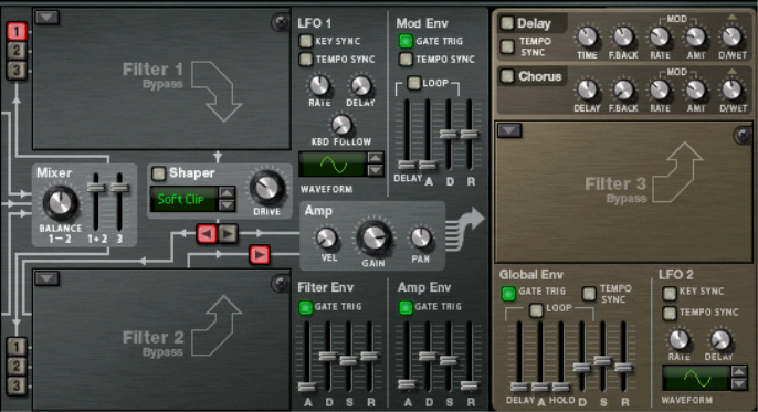
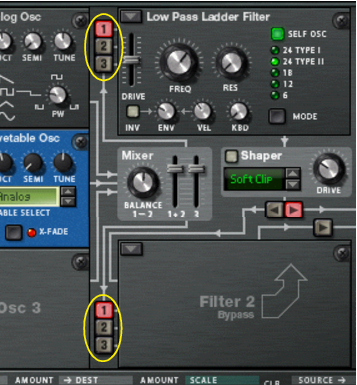
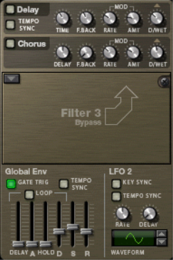
Thor has three open Filter slots, two in the Voice section (which act per-voice) and one in the Global section which is global for all voices (see “Global Filter slot”).
*
On the pop-up you can select between 4 filter types and bypass mode. Available filter types are Ladder LP, State Variable, Comb and Formant, each described separately below.
The following general rules apply:
*
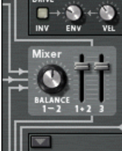
The pre-defined routings of the three oscillators into the Filter 1-2 sections is described in the “Basic connections - a tutorial” passage.
Common parameters
As with the open oscillator slots, there are certain parameters which are common for all filter types.
These are as follows:
*
This works slightly differently for the Formant filter - see “Formant filter”.
*
Some filter types (Ladder/State Variable/Comb) can “self oscillate” and be used as extra oscillator sources.
*
*
In other words, for this parameter to have any effect it requires that the “ENV” parameter is set to a value other than zero.
*
*
By driving the filter harder you can add further character to the sound.
*
Ladder LP Filter
The Ladder LP filter is a low-pass filter inspired by the famous voltage controlled filter patented by Dr. Robert Moog in 1965. The name originates from the ladder-like shape of the original transistor/capacitor circuit diagram.
The original filter also had certain non-linear characteristics which contributed to the warm, musical sound it is renowned for. These characteristics are faithfully reproduced in the Ladder LP filter.
There is also a built-in shaper in the feedback (self-oscillation) loop. If self-oscillation is activated (see below), the shaper will distort the sound to produce these non-linear characteristics. To adjust the intensity of this distortion you use the Drive parameter.
*
24dB slope comes in two different types:
Note that “Self Osc” (see below) must be activated for the shaper to operate.
*
Self-oscillation can be switched on or off by using the “SELF OSC” button. The “KBD” knob governs how the frequency tracks the keyboard, turned fully clockwise will produce 12 semitones/octave tracking.
State Variable Filter
This is a multi-mode filter which offers 12 dB/octave slope Lowpass (LP), Bandpass (BP), Highpass (HP), plus Notch and Peak filter modes which are sweepable between HP/LP states, similar to the vintage Oberheim SEM filter.
The filter modes are as follows:
*
Lowpass filters let low frequencies through and cut off high frequencies. This filter type has a 12dB/Octave slope.
*
Bandpass filters cut both high and low frequencies, leaving the frequency band in between unaffected. Each slope in this filter type is 12 dB/Octave.
*
Highpass filters let high frequencies pass and cut off low frequencies. This filter type has a 12dB/Octave slope.
*
The “LP/HP” knob associated to these two filter modes can modulate the state of the filter from low-pass to high-pass. If the knob is in the mid-position, you get a Peak or Notch filter slope (depending on the mode). The HP/LP parameter can be assigned as a modulation destination.
*
Self-oscillation can be switched on or off by using the “SELF OSC” button. The “KBD” knob governs how the frequency tracks the keyboard, turned fully clockwise will produce 12 semitones/octave tracking.
Comb filter
The Comb filter can add subtle pitch variations and phasing-like effects to sounds.
*
A comb filter causes resonating peaks at certain frequencies. Comb filters are used in various signal processing devices like flangers, and produces a characteristic swooshing sound when the frequency is swept.
*
The main audible difference is that negative Comb mode causes a bass cut.
*
This filter will produce a pitch with high Resonance settings combined with low frequency settings.
Formant filter
The Formant filter type can produce vowel sounds. There are no Frequency or Resonance parameters, instead you have a horizontal “X” parameter slider and a vertical “Y” parameter slider that operate together to produce the various filter formant characteristics.
*
Horizontal movement changes the “X” parameter, and vertical movement the “Y” parameter.
*
The parameter can be CV controlled.
*
Gender can also be CV controlled.
Shaper
Waveshaping is a synthesis method for transforming sounds by altering the waveform shape, thereby introducing various types of distortion. The Shaper can radically transform the sound or just add a little warmth, depending on the mode and other settings.
*
*
*
Tip: By raising the Filter 1 Drive parameter you can add even more grit and distortion to the Shaper output.
*
These modes are; Soft and Hard clip, Saturate, Sine, Bipulse, Unipulse, Peak, Rectify and Wrap. Exactly how the various modes affect the sound depends on many factors, and there is a slightly random element to the resulting distortion. We recommend simply trying the different modes to hear what happens - many interesting types of distortion of the original signal are guaranteed!
Amp section
The Amp (amplifier) section has two inputs (from Filter 1 & 2) and one output that is routed to the Global section (and on to the Master Level and the Main Outputs).
*
*
By applying modulation to this parameter, you can make individual voices appear in different stereo positions when you play.
LFO 1
An LFO (Low Frequency Oscillator) is used for generating cyclic modulation. A typical example is to have an LFO modulate the pitch of an oscillator to produce vibrato, but there are countless other applications for LFOs.
*
I.e. if LFO 1 modulation of a parameter is assigned, an individual LFO cycle will be triggered for each note you play.
*
The following parameters are available for LFO 1:
Envelope sections
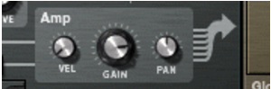
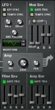
There are three Envelope generators in the Voice section. These are the Amp envelope, the Filter envelope and the Mod envelope. Each voice played has a separate envelope. There is also an additional Global Envelope which is described separately - see “Global Envelope”.
*
Note that envelope control of filter frequency can be switched off in each Filter section (the Env parameter can be set to 0), so the Filter Envelope can be used to control other parameters as well.
*
Similarly, the Amp envelope can also be used to control other parameters, but in the Voice section you cannot switch off or bypass the Amp Envelope - if no voice is active (i.e. if there is no gate trigger input to the Amp envelope) there will be no output from oscillators or any external audio source routed to the Voice section.
*
This is done in the Modulation section.
Filter Envelope
The Filter Envelope is a standard ADSR envelope as used in the Subtractor.
*
Please refer to the Subtractor chapter for a description of these parameters.
*
“Gate Trig” should normally be activated.
*
Attack: 0 ms - 10,3 s / Decay and Release: 3 ms - 29,6 s. Sustain is not set as a time but as a level (from Off to 0dB).
Amp Envelope
The Amp Envelope is also a standard ADSR envelope.
*
Please refer to the Subtractor chapter for a description of these parameters.
*
“Gate Trig” should normally be activated.
*
Mod Envelope
This is a general purpose ADR (Attack, Decay, Release) envelope with a pre-delay stage before the Attack phase. The Delay to Decay phase can also be looped. Apart from standard Attack, Decay and Release stages the Mod Env has the following parameters:
Global section
The Global section contains parameters that affect all voices. It contains two effects, an open filter slot, the Global Envelope and LFO 2.
Effects section
There are two global mono in/stereo out effects, a Delay and a Chorus. These effects affect all voices coming from the Amp section equally if activated. The effects are placed after the Global Filter in the signal chain.
*
Chorus vs. Delay differ only in the delay time range - Chorus is for chorus effects, i.e. short delays, whereas Delay produces echo effects.
*
This is set with the Tempo Sync button - if on the delay time is set in beat resolutions synced to the main sequencer tempo.
*
“Rate” controls LFO speed and “Amount” the Stereo width.
*
Global Filter slot
This is the Filter 3 slot which can be loaded with one of the filter types. Filter 3 is basically set up as the other filter slots. The difference is that all voices are mixed together before entering the filter. The “ENV” parameter governs modulation by the Global Envelope. If you play one note the filter envelope will trigger. Adding new notes while a note is still held down (legato) will not trigger the filter envelope.
See “Filter slots” for a description of the filter types.
Global Envelope
The Global Envelope 4 is an advanced envelope that is free to use for whatever purpose, but remember it is “single trigger” so it will not retrigger legato notes as explained above. It is an ADSR envelope with a pre-delay stage and a hold stage before the decay phase. You can make it Loop and Sync the time settings to the song tempo.
Apart from standard ADSR parameters, the Global Envelope has the following parameters:
LFO 2
*
*
The following parameters are available for LFO 2:

Thor Polysonic Synthesizer : Using the Programmer