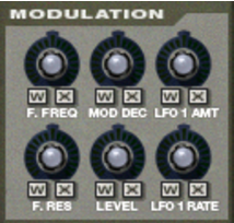
As previously described, the Modulation wheel (and the External Control wheel) can be used for controlling various parameters. These controls allow you to define which parameters the wheels should modulate and to what extent.
These are used for selecting the source that should control the parameter, and represent the “Modulation Wheel” and the “External Control wheel” respectively.
|
|
By turning the knobs, you decide how much the modulation and/or external control wheel should modulate the corresponding parameter.
|
Note that all of the control knobs are bi-polar, which means that they can be set to both positive and negative values. Positive values are set by turning the knobs to the right, and negative values are thus set by turning the knobs to the left:
|
•
|
|
•
|
There is one exception to these rules, and that is the LFO 1 Amt control, which works in a slightly different way. See below for more information about this.
This sets modulation control of the Decay parameter in the Modulation Envelope (see “The Modulation Envelope”).
This determines how much the amount of modulation from LFO 1 is affected by the Modulation wheel and/or the External Controller wheel. It does this by “scaling” the amounts set with the three destination knobs in the LFO 1 section (Pitch, Filter and Level, see “The LFOs”). We’ll explain this with an example:
To use the Modulation Wheel to increase pitch modulation (vibrato), proceed as follows:
|
4.
|
To instead use the Modulation wheel to decrease vibrato, process as follows:
|
4.
|
This sets the amount of amplitude envelope modulation of each zone’s level. The level set here will be the level of the highest point of the Amp Envelope.
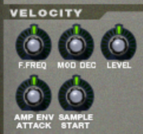
Velocity is used for controlling various parameters according to how hard or soft you play notes on your keyboard. A typical use of velocity control is to make sounds brighter and louder if you strike a key harder. By using the knobs in this section, you can control if and how much the various parameters will be affected by velocity.
Just like the modulation controls, all of the velocity control knobs are bi-polar, and can be set to both positive and negative values.
This sets velocity control of the Decay parameter in the Modulation Envelope (see “The Modulation Envelope”).
This sets velocity control of the Attack parameter in the Amplitude Envelope (see “The Amplitude Envelope”).
This sets velocity control of the Sample Start parameter (see “Sample Start and End”), so that it will be offset forwards or backwards, according to how hard or soft you play.
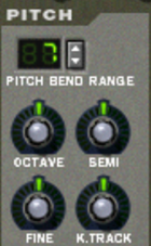
This lets you set the amount of pitch bend, i.e. how much the pitch changes when your turn the pitch bend wheel fully up or down. The maximum range is +/- 24 semitones (2 Octaves).
|
•
|
|
•
|
|
•
|
|
•
|
When turned all the way down, all keys play the same pitch. This can be useful for percussion like timpani where you might want to play the same pitch from a range of keys.
|
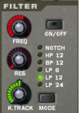
Filters can be used for shaping the character of the sound. The filter in NN-XT is a multimode filter with six different filter types.
To select a filter mode, either click the Mode button in the bottom right corner or click directly on the desired filter name so that it lights up:
|
•
|
The notch filter is used for cutting off frequencies in a narrow frequency range around the set cutoff frequency, while letting the frequencies below and above through.
|
•
|
This is a highpass filter with a 12 dB/Octave roll-off slope. A highpass filter cuts off low frequencies and lets high frequencies pass. That is, frequencies below the cutoff frequency are cut off and frequencies above it pass through.
|
•
|
This is a bandpass filter with a 12 dB/Octave roll-off slope. A bandpass filter could be viewed as the opposite of a notch filter. It cuts off both the high and the low frequencies, while frequencies in the band range pass through.
|
•
|
This is a lowpass filter with a gentle, 6 dB/Octave slope. A lowpass filter is the opposite of a highpass filter. It lets the low frequencies through and filters out the high frequencies. This filter has no Resonance.
|
•
|
|
•
|
|
•
|
This is used for setting the filter cutoff frequency. The cutoff frequency determines the limit above or below which frequencies will be cut off depending on the selected filter type. In the case of a lowpass filter for example, frequencies below the cutoff frequency will be allowed to pass through, while frequencies above it will be cut off. The farther to the right you turn the knob, the higher the cutoff frequency will be.
|
|
|
•
|
Technically, this knob controls feedback of the output signal from the filter, back to its input. Acoustically it emphasizes frequencies around the cutoff frequency. For a lowpass filter for example, increasing Res will make the sound increasingly more hollow until the sound starts “ringing”. If you set a high value for the Res parameter and then vary the filter frequency, this will produce a classic synthesizer filter sweep.
For the notch and bandpass filter types, the Resonance setting instead adjusts the width of the band. That is, the higher the resonance setting, the narrower the band will be where frequencies are cut off (notch) or let through (Bandpass).
|
•
|
This lets you activate and control keyboard tracking of the filter frequency. If keyboard tracking is activated, the set cutoff frequency of the filter will change according to the notes you play on your keyboard. That is, if you play notes higher up on the keyboard, the filter frequency will be raised and vice versa.
When the knob is set to its center position, filter frequency is adjusted so that the harmonic content remains constant across the keyboard.
Keyboard tracking is deactivated by default (the knob all the way to the left). This means that the filter frequency will remain unchanged regardless of where on the keyboard you play.
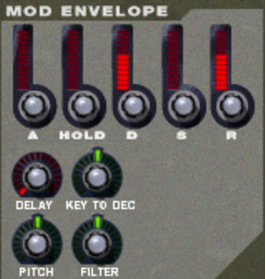
The Modulation Envelope parameters let you control how certain parameters, or destinations, should change over time - from the moment a note is struck to the moment it is released again.
|
•
|
|
•
|
When you press a key on your keyboard, the envelope is triggered. The attack parameter then controls how long it should take before the controlled parameter (pitch or filter) reaches the maximum value, when you press a key. By setting attack to a value of “0”, the destination parameter would reach the maximum value instantly. By raising the attack parameter, the value will instead slowly “slide” up to its maximum.
|
•
|
This is used for deciding how long the controlled parameter should stay at its maximum value before starting to decrease again. This can be used in combination with the Attack and Decay parameters to make a value reach its maximum level, stay there for a while (hold) and then start dropping gradually down to the sustain level.
|
•
|
After the maximum value for a destination has been reached and the Hold time has expired, the controlled parameter will start to gradually drop down to the sustain level. How long it should take before it reaches the sustain level is controlled with the Decay parameter. If Decay is set to “0”, the value will immediately drop down to the sustain level.
|
•
|
The Sustain parameter determines the value the envelope should drop back to after the Decay. If you set Sustain to full level however, the Decay setting doesn’t matter since the value will never decrease.
A combination of Decay and Sustain can be used for creating envelopes that rise up to the maximum value, then gradually decrease to, and stay on a level somewhere in-between zero and maximum.
|
•
|
This works just like the Decay parameter, with the exception that it determines the time it takes for the value to fall back to zero after the key is released.
|
•
|
This is used for setting a delay between when a note is played and when the effect of the envelope starts. That is, the sound will start unmodulated, and the envelope will kick in after you have kept the key(s) pressed down for a while. Turn the knob to the right to increase the delay time. If the knob is set all the way to the left, there will be no delay.
By using this, you can cause the value of the Decay parameter (see above) to be offset depending on where on your keyboard you play. If you turn the knob to the right the decay value will be raised the higher up you play, and turning the knob to the left will lower the decay value the higher up you play. With the knob in the center position, this parameter is deactivated.
|
•
|
This will make the envelope modulate the pitch, as set in the Pitch section (see “The Pitch section”). Turn the knob to the right to raise the pitch and to the left to lower the pitch. In the middle position, pitch will not be affected by the envelope.
|
•
|
This will make the envelope modulate the cutoff frequency of the Filter (see “The Filter section”). Turn the knob to the right to increase the frequency and to the left to lower the frequency. In the middle position, the envelope will have no effect on the cutoff frequency.
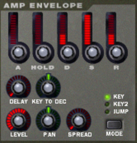
The Amplitude Envelope parameters let you control how the volume of a sound should change over time - from the moment a note is struck to the moment it is released again.
Most of the Amplitude Envelope parameters are identical to those of the Modulation Envelope. So for a detailed description of the following parameters, please refer to the modulation envelope section in “The Modulation Envelope”:
|
•
|
|
•
|
|
•
|
|
•
|
|
•
|
|
•
|
|
•
|
These two parameters are used for controlling the stereo (pan) position of the sound. The Spread knob determines the sound’s width in the stereo image (how far left – right the notes will be spread out). If this is set to “0”, no spread will take place. The Mode selector switch is used for choosing which type of spread you want to apply:
|
| Mode
|
|||
|
|||
|
•
|
This controls the stereo balance of the output pair to which a zone is routed. In the middle position, the signal appears equally strong on the left and right channel in a stereo pair. By turning the knob to the left or right, you can change the stereo balance.
Note that if you for instance turn the Pan knob all the way to the left, you cause the signal to be output from the left channel of the stereo pair only.
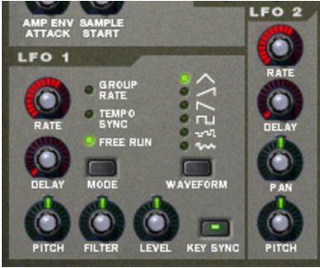
NN-XT features two Low Frequency Oscillators - LFO 1 and LFO 2. “Normal” oscillators generate a waveform and a frequency, and produce sound. Low frequency Oscillators on the other hand, also generate a waveform and a frequency, but there are two major differences:
The most typical use of an LFO is to modulate the pitch of a sound (generated by an oscillator or - in the case of NN-XT - a sample), to produce vibrato.
|
•
|
LFO 2 is always key synced, that is, each time you press a key, the LFO waveform starts over from scratch. LFO 1 can be switched between key synced and non-key synced modes.
|
This knob controls the frequency of the LFO. For a faster modulation rate, turn the knob to the right. The Rate knob of LFO 1 is also used for setting the timedivision when synchronizing the LFO to the song tempo (see below).
This can be used for setting a delay between when a note is played and when the LFO modulation starts kicking in (gradually). This way, you can make the sound start unmodulated, and then have the LFO modulation start after you have kept the key(s) pressed down for a while.
In this mode, the LFO will run at the rate set for its group in the group section, rather than at the rate set here (see “Group parameters”). This way, all zones in the group will have the exact same modulation rate.
|
|
When tempo sync is activated, the Rate knob is used for selecting the desired timedivision. Turn the Rate knob and observe the tool tip for an indication of the timedivision.
|
|
•
|
In free run mode, the LFO simply runs at the rate set with the Rate parameter. Furthermore, if Key Sync is deactivated, the modulation cycle will not be retriggered each time you press a key - it will run continuously.
|
| Waveform
|
|||
|
|||
|
|||
|
•
|
This will make the LFO modulate the pitch, for vibrato, trills, etc. It can be set to -2400 – 0 – 2400 cents which equals 4 octaves. The set pitch will change up and down by this amount, with each modulation cycle. Turning the knob to the right will make the modulation cycle start above the set pitch, while turning it to the left will invert the cycle. Keeping this in the middle position means that the pitch will not be affected by the LFO.
|
•
|
This will make the LFO modulate the cutoff frequency of the Filter, for auto-wah effects, etc. The positive/negative effect is the same as for pitch.
|
•
|
This will make the LFO modulate NN-XT’s output level, for tremolo effects, etc. The positive/negative effect is the same as for pitch.
|
•
|
This makes the LFO modulate the pan position of a zone. The sound will move back and forth in the stereo field. Turning the knob to the left makes the sound move from left to right, and turning it to the right thus makes it move from right to left. The middle position provides no modulation at all.
|
•
|
