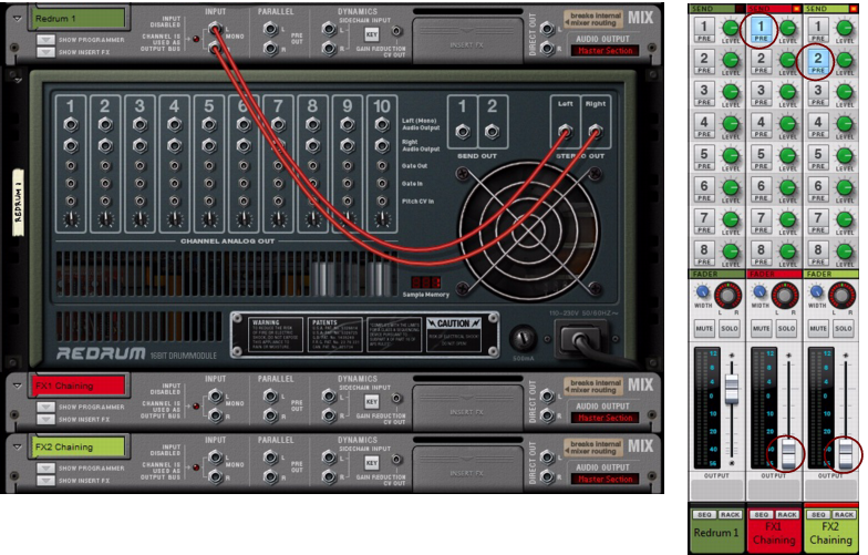
The Redrum Drum Module and the Mixer 14:2 and 6:2 devices have separate Send FX connectors where you can add send effects individually for each device. The Redrum and Mixer devices also have separate Send FX level pots for each drum/mixer channel so that you could set the send effect levels individually for each drum/mixer channel in the device.
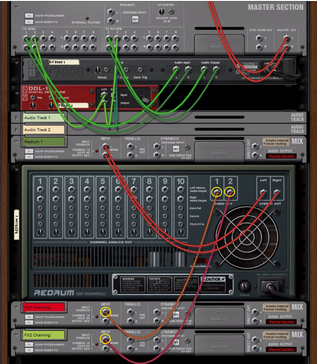
Let’s say you want to add a Redrum device and use two of the Main Mixer’s Send FX, but with individual settings for each of the Redrum device’s internal channels. In the example below, we’re going to chain the two Send Outs from the Redrum device to two send effects in the Main Mixer:
|
2.
|
In this example, we activate the Send FX 1 bus on the FX1 Chaining channel and the Send FX 2 bus on the FX 2 Chaining channel. The Send FX 1 has a reverb connected and the Send FX 2 has a delay connected.
This way, the effect signals won’t be mixed with the rest of the Main Mixer channel signals in the mix bus, but are kept isolated in the Send FX busses. Now, our setup should look like this in the rack and in the Main Mixer:
|
4.
|
Connect the Send Out 1 and 2 of the Redrum device to the Left inputs of each of the “FX 1 Chaining” and “FX 2 Chaining” Mix Channel devices.
|
Now, you have individual send levels for each of the Redrum device’s internal channels - and are still able to use the Send FXs in the rest of the Main Mixer channels like before.
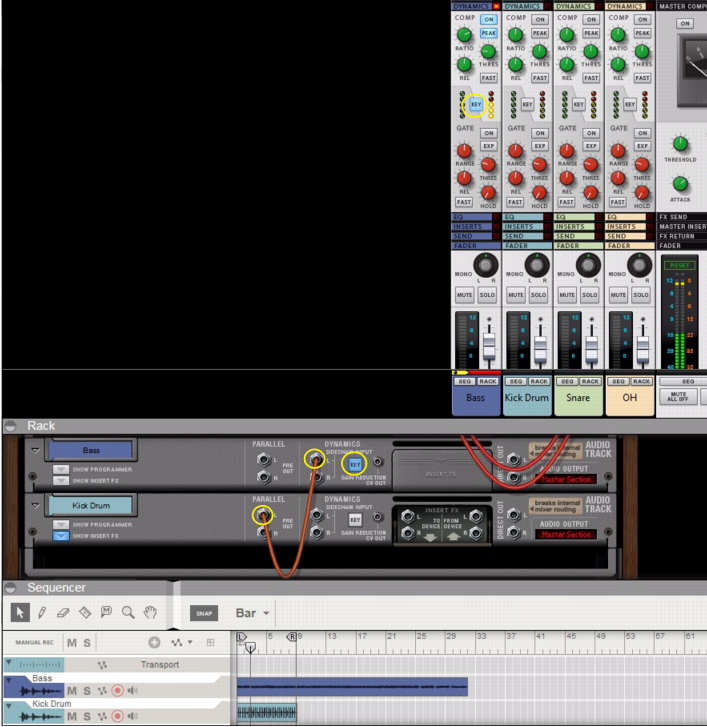
Compression sidechaining is a feature which lets you control the Compressor, not from the internal channel signal, but from an external signal. A typical use case would be to let the signal from a kick drum channel control the compression of the bass channel. The result would be that the bass signal is compressed each time the kick drum signal is present on the sidechain input, allowing the kick sound to momentarily suppress the bass sound.
The example below shows an audio track with a kick sound that is tapped from the Kick Audio Track device’s Parallel output and routed to the Dynamics Sidechain input of the Bass Audio Track device.
If you want to use compression sidechaining of several (destination) channels from a single source channel, there are some options of doing that:
|
•
|
If you are already using both Parallel outputs for sidechaining, tap an additional sidechain signal from one of the Insert FX “To Device” outputs of the source channel.
|
|
•
|
Use a “Spider Audio Merger & Splitter” device to split the sidechain signal from the Parallel outputs and/or Insert FX “To Device” output into several signals.
|
Each of these signals can then be individually routed to each Sidechain Input of the desired destination Audio Track/Mix Channel devices.
|
•
|
Create an Output Bus (sub-mixer) and route all (destination) channels you want to control to this Output Bus. Then, route the sidechain signal from the source channel device to the Sidechain Input of the Output Bus Mix Channel device.
|
See “Output Busses” for information.
Another typical application for compression sidechaining is to use the internal signal of the channel, filter it, and then feed to the compressor via “internal” sidechaining. This type of internal sidechaining can be used for de-essing, for example. No additional patching is required for this; you only have to activate the “Filters to Dynamics Sidechain” button in the Filter or EQ sections. See “About the Filters To Dynamics Sidechain button”.
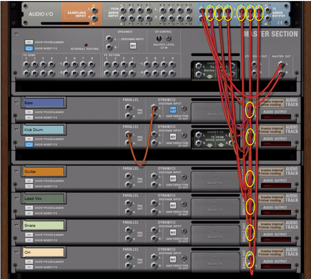
The Mix Channel and Audio Track devices feature Direct Out connectors. By patching cables into these outputs, you break the internal signal chain from the device to the Master Section, and can route the channel output signals directly to the Reason Hardware Device’s outputs. This is a very nice feature if you want to use outboard mixing or summing - or if you’re using ReWire (see “ReWire”) to route individual channel signals to another application.
The example below shows how to route the Direct Outs of a number of Audio Track devices to separate outputs of the Reason Hardware Interface:
Direct routing of individual channel outputs to individual outputs on the Reason Hardware Interface.
|
|
Using the Direct Outs will break the internal P-LAN routing to the Master Section device. This is indicated by the red dashes (---) in the Audio Output display on the Audio Track/Mix Channel devices.
|
When you record on an audio track, the input signal is routed “dry” to the audio track. Then, when you play back the recorded audio, the signal goes via the channel strip, with all its settings and any Insert FX etc. However, there might be situations where you want to record a processed signal to the audio track. For example, if you record an electric guitar, you might want to record it with distortion effects or similar.
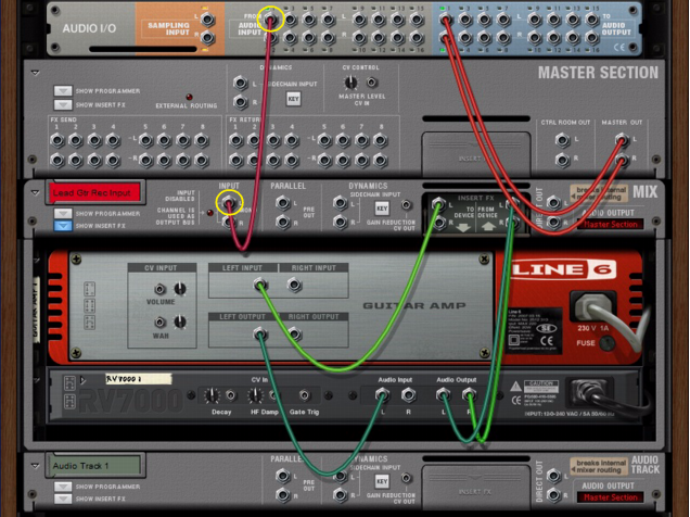
The example below shows a typical setup where a separate Mix Channel device is used for processing the input signal before it’s routed to the audio track for recording:
This manual patching from the Hardware Interface is made to route the input signal directly to the Mix Channel device, where we have our effects.
|
6.
|
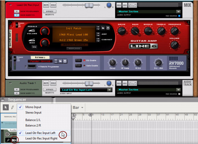
Finally, select the Mix Channel device as Input on the Audio Track in the sequencer (or in the Audio Input selector on the Audio Track device in the rack).
|
Now, you can begin recording on the Audio Track according to the standard recording procedures described in “General recording procedure”. The signal will be processed by the Insert FX of the Mix Channel device before being recorded on the track.
With this setup, you will always hear the sound of the input processed through the Amp device - just as if you had a real hardware amp turned on and mic'ed in the studio. If you don't want the “Lead Gtr Rec Input” Mix channel to be heard, just mute it in the Main Mixer.
