The Combinator : Using Modulation Routing

Using Modulation Routing
The Modulation Routing section to the right on the Editor panel allows you to assign any parameter or function in devices included in a Combi to any of the virtual controls on the Control panel.
You can also control Combi parameters by connecting external CV modulation sources to any of the Source CV inputs on the back of the unfolded Editor panel, see “Wheel CV In and Source CV In”.
About Rotary/Slider and Switch controls
The virtual Rotary/Slider and Switch controls operate much like the equivalent controls on the real devices:
Worth noting is that there are buttons on several Reason devices that will step through a series of values, for example LFO Waveform buttons. If LFO Waveform is assigned to one of the virtual Buttons you will only be able to switch between two of the six LFO waveforms (which waveforms is determined by the Min/Max range).
Most sliders and rotary knobs on the actual devices have the standard 0-127 or -64 to 63 range. Selectors and spin controls can have any value range.
About the CV Inputs
On the back of the Editor panel are CV Modulation Inputs for connecting external CV signals to modulate any of the parameters that are accessible in the Target section in the Editor, see “Wheel CV In and Source CV In”.
Assigning panel controls to device parameters
Assigning Combinator panel controls to device parameters can be done in two different ways:
1.
Assigning the “Master Volume” control on an Europa device to the “Level” control on the Combinator panel.
If you chose the method described above you can continue directly to step 4 below in this description.
*
The Modulation Routing section to the right contains four columns:
Each field can be changed to any Control/Slider/Switch/CV Input or Performance Controller by clicking the arrow and selecting from the drop-down list.
Lastly in each Target drop-down list is the option to receive note data or not. This is useful if you want to temporarily enable/disable MIDI Note input for specific devices, e.g. to temporarily enable layered instruments - or switch instrument playback.
It’s also possible to set the Min value higher than the Max value, meaning that the value will decrease when you turn up the knob/slider.
2.
Setting the “Level” Combinator panel control as Source.
3.
In the drop-down, all the available parameters for the device are listed.
Assigning the Europa “Master Volume” parameter as Target.
4.
By the maximum available range is set by default:
The result is that the Target parameter value will decrease when you turn up the Source knob/slider, and vice versa. Here is an example of how to reverse the range for a parameter:
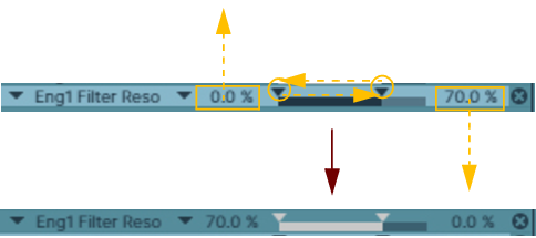
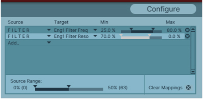
The Filter Reso parameter edited to have a reversed Range, as indicated by the light gray Range bar.
Source Range for Rotary 1 set to 50-100%.
5.
This means that you can create multi-function controls that operate simultaneously on several parameters. E.g. if you have two Subtractors and a Malström in a Combi you could create a “master” filter cutoff knob, that controls this parameter for all three devices. See “Controlling multiple Target parameters differently from a single Source control” for an example.
*
Controlling multiple Target parameters differently from a single Source control
You can also have the same Source control assigned to multiple Target parameters on the same device. In the example below the “Eng1 Filter Freq” and the “Eng1 Filter Reso” parameters on the Spectral Filter in a Europa device are assigned to the same FILTER control on the Combinator panel:
The “Eng1 Filter Reso” parameter Range is reduced and reversed (light gray Range bar), so when you turn up the FILTER knob on the Combinator panel, the Filter Frequency is raised but the Resonance is decreased. The “Eng1 Filter Reso” parameter also has the Source Range set to 0-50%, which means the Resonance will decrease only during the first half of the FILTER knob range.
The picture below shows how the “Eng1 Filter Freq” and “Eng1 Filter Reso” parameters are affected when you turn up the FILTER knob on the Combinator panel. You can also see the differences in the Spectral Filter display:
Controlling both the Freq and Reso parameters from the FILTER control on the Combinator panel.
Controlling a single Target parameter from multiple Source controls
This is also possible, by simply selecting the same Target parameter from different Source controls in the Modulation Routing section.

The Combinator : Using Modulation Routing