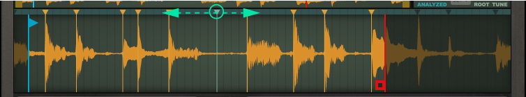
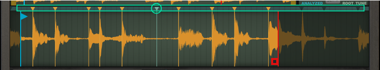
Here is where you load/sample the audio for the currently selected Slot. The Waveform display differs somewhat, depending on which Slot Mode you have selected (see “Slot Mode”).
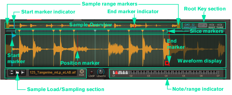
See the “Sampling” chapter for more information about setting up and using Reason for sampling.
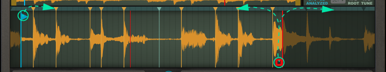
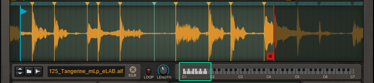
Note that the Start and End markers cannot be set in reversed order. If you want to play the sample backwards, from the End marker to the Start marker, click the Reverse button (see “Reverse”).
|
|
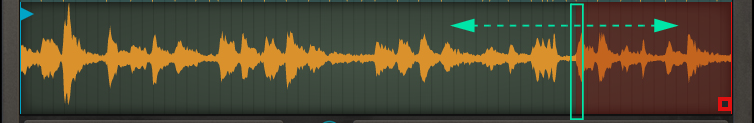
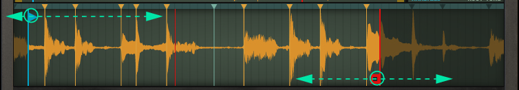
If you are playing back the sample reversed (see “Reverse”) the looped region originates from the Start Marker instead and is displayed in transparent blue.

|
|
|
|
|
|

Depending on which Stretch type (see “Stretch”) is currently selected, the sonic result will vary. If you have selected the Tape Stretch type (see “Tape”), the Speed knob also affects the pitch. Note that the Speed can be set all the way down to 0%, i.e. “stop”. Great for Tape Stop effects in Tape mode and for static playback in other Stretch types, for example.

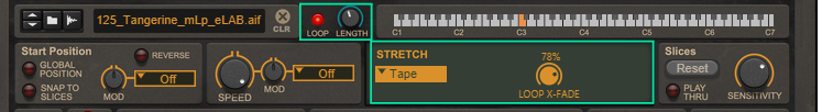
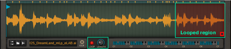
With the Tape stretch type selected, there is a Loop X-Fade knob present. This controls the crossfade amount when the Loop function is active for the sample/slices (see “Loop and Loop Length”).


|
|
The Melody stretch type is well suited if you are using the Loop function (see “Loop and Loop Length”), since it usually reduces clicks/pops at the loop point.
|


|
|
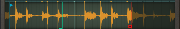
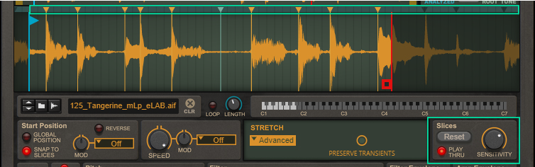
Even though slices are the core of Slice mode, they are available in the other modes too. They can be used for snapping the Start position (see “Setting the sample start and end”) - either when you drag it manually or when you modulate or automate it.
|
|
|
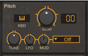
Note that if you are using the Tape Stretch type (see “Tape”), the pitch settings also affect the playback speed.
|
|
|
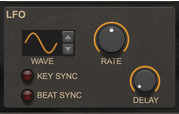
By using the LFO Scale function (see “LFO Scale”), you can gradually introduce the LFO modulation amount by using the Mod Wheel.
|
|
•
|
|
•
|
|
•
|
|
•
|
|
•
|
|
•
|
|
•
|
|
•
|
|
|
|
|
By using the LFO Scale function (see “LFO Scale”), you can gradually introduce the LFO modulation amount by using the Mod Wheel.
|
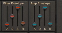
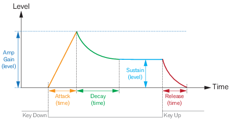
This is the maximum level the envelope will reach after the Attack stage is completed (see “A(ttack)”.).
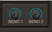
The Send knobs can be used for tapping the output signal of the Slot to the corresponding FX Send Out jacks on the rear panel (see “FX Send Out”). You could then route the signals to external effect devices and then further to a separate mixer/audio channel.