Loading and saving patches is done in the same way as with any other internal Reason device, see “Loading patches” and “Saving patches” for details.

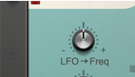
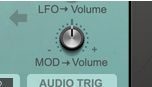
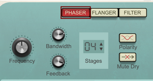
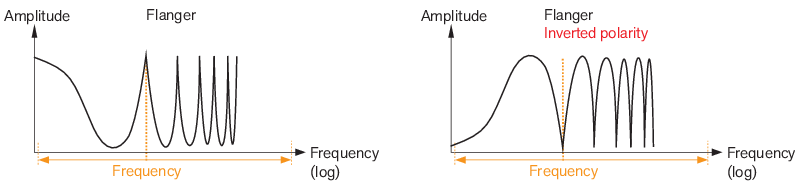
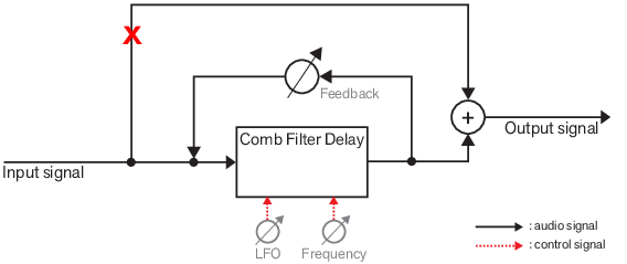
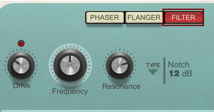
This controls the modulation amount from the LFO (see “LFO”) to the Frequency control of the Phaser (see “Frequency”), Flanger (see “Frequency”) and Filter (see “Frequency”) section.
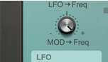
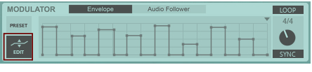
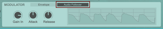
This controls the modulation amount from the Modulator (see “The Envelope Modulator” and “The Audio Follower Modulator”) to the Frequency control of the Phaser (see “Frequency”), Flanger (see “Frequency”) and Filter (see “Frequency”) section.
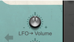
This controls the modulation amount from the LFO (see “LFO”) to a separate built-in amplifier. The control is bipolar, which means that negative values will invert the modulation.
This controls the modulation amount from the Modulator (see “The Envelope Modulator” and “The Audio Follower Modulator”) to a separate built-in amplifier.


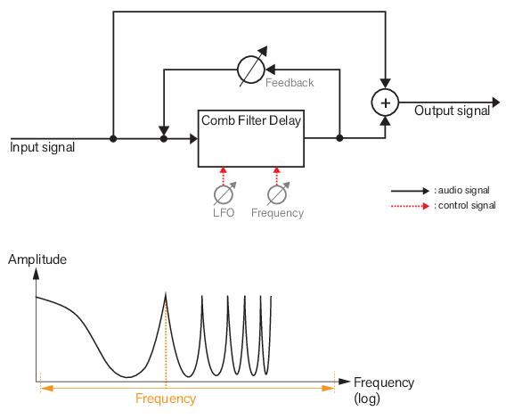


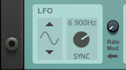
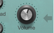
The LFO can be used for cyclic modulation of the Frequency parameter of the Phaser/Flanger/Filter section - and/or for modulating the Volume. The LFO Rate can also be synced to the Reason sequencer. You can also modulate the LFO Rate from the Modulator (see “The Envelope Modulator” and “The Audio Follower Modulator”).


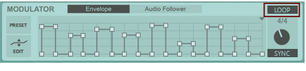
If you like, you can modulate the LFO Rate from the Modulator signal (see “The Envelope Modulator” below). If the LFO is in SYNC mode, modulating the Rate will force the LFO to switch between the sync divisions.
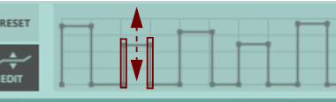
|
•
|
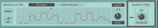
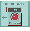
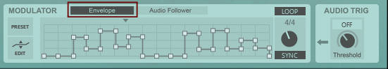
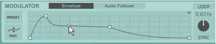
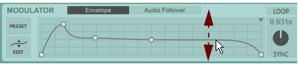
The envelope/loop playback starts as soon as there is audio present in Sweeper - or you can trigger playback using the Audio Trig function (see “Audio Trig”) or a CV trig signal on the rear panel (see “Trig Envelope”) instead.
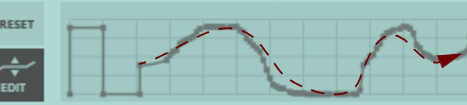
|

|
|